INTRODUCTION
General. The information on the following pages is to
provide the installer the necessary information to
properly install the Unico System electric furnaces. The
electric furnaces are designed to provide primary or
auxiliary heating. The available model numbers,
capacity, and air handler compatibility are shown in the
Table 1.
Table 1. Electric Furnaces
LOCATION
Before installing the furnace, inspect the unit
thoroughly for shipping damage. Check all porcelain
insulators for any breaks and inspect the furnace
element wire to see that none have been deformed.
Check the heating elements for loose connections that
could cause overheating. If any shipping damage is
found, notify the carrier immediately.
Install the furnace by attaching it directly to the air
handler using the adapter collar provided with the
furnace. Alternately the furnace can be placed in the
duct system to act as a duct heater. For this
configuration, an additional duct collar (see table 6
below) must be ordered to correctly install the heater.
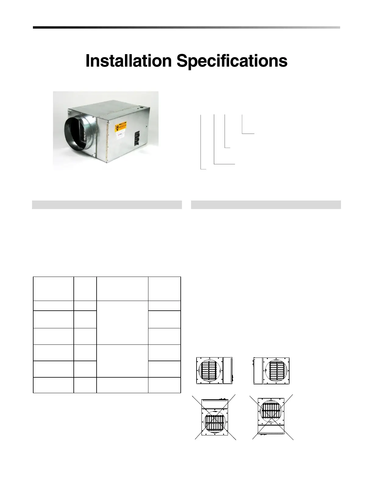
In either configuration, position the unit so the arrow
label on the cover of the electric furnace control box is
in the direction of the airflow. The electric furnace
control box can be placed on either side of the unit as
shown in Figure 1.
 Loading...