The Unicore UFirebirdII-UC6580 Evaluation Kit (EVK) is designed for the function and performance testing of the UC6580 chip. This document serves as a user manual for technicians familiar with GNSS receivers.
Function Description
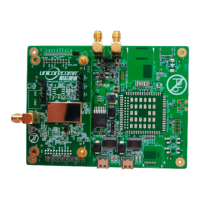
The EVK facilitates comprehensive testing of the UC6580 chip, primarily focusing on its GNSS receiver capabilities and power consumption in various operating modes. It comprises two main components: a bottom board and a GNSS adapter. The bottom board connects to the GNSS adapter via a connector, providing the necessary interfaces and power for the adapter and the UC6580 chip.
The kit supports communication with a host PC via two Type-C USB2.0 interfaces (J17 and J6), labeled USB1 and USB2. These interfaces correspond to UART1 and UART2 of the GNSS adapter, respectively. While both UARTs can be used for host communication, only UART1 is capable of firmware upgrades.
For antenna connectivity, the bottom board features two SMA interfaces: J16 for the SPEED signal and J12 for the FWD signal. These signals require a voltage between 5 V and 15 V. The SPEED signal supports phase switching, controlled by jumper J20, where connecting pins 1 and 2 results in a positive signal, and connecting pins 2 and 3 results in a negative signal (default is pins 1 and 2 connected). The GNSS adapter includes a dedicated antenna interface (J4) for connecting a GNSS antenna. For external active antennas, jumper caps must be installed on J11 (VDET jumper) and J3 (VANT jumper), with the antenna voltage being VDDIO-0.1V.
A chip reset button (K4) is present on the bottom board for convenience. Communication mode selection is managed by jumper J25 on the bottom board. Installing the jumper cap (ON) activates SPI mode, while removing it (OFF) enables UART and I2C_slave mode (default is OFF). In SPI mode, SPI_SCK serves as the SCL testing point, and SPI_CS as the SDA testing point.
The EVK also includes status indicators for various functions:
- D71 (UART1-RX): Lights up when receiving data; otherwise off.
- D72 (UART1-TX): Lights up when sending data; otherwise off.
- D73 (UART2-RX): Lights up when receiving data; otherwise off.
- D74 (UART2-TX): Lights up when sending data; otherwise off.
- D80 (Power indicator): Lights up when power is supplied; otherwise off.
- D66 (PPS status indicator): Lights up with low level voltage; off with high level voltage.
The GNSS adapter has three power supply interfaces:
- J1 (VDDIO interface): Pin 1 connects to 3.3 V power from the bottom board, Pin 2 is VDDIO power supply interface.
- J9 (Backup battery interface): Pin 1 connects to the bottom board, Pin 2 is V_BACK power supply interface.
- J10 (DCDC_IN interface): Pin 1 connects to the bottom board, Pin 2 is DCDC_IN power supply interface.
By default, the jumper caps are installed, and the adapter is powered by the bottom board. To use an external voltage to power the interfaces, connect the power to pin 2.
Important Technical Specifications
- USB Interfaces: Two Type-C USB2.0 (J17, J6). USB1 for UART1 and firmware upgrade; USB2 for UART2.
- Antenna Interfaces:
- Bottom Board: J16 (SPEED signal SMA), J12 (FWD signal SMA). Voltage range: 5 V to 15 V.
- GNSS Adapter: J4 (GNSS RF interface).
- External Active Antenna Support: J11 (VDET jumper) and J3 (VANT jumper) for antenna voltage (VDDIO-0.1V).
- Communication Modes: SPI (jumper J25 ON), UART and I2C_slave (jumper J25 OFF, default).
- Power Supply: 5 V via USB2.0 (J17 or J6).
- Power Consumption Measurement: Supports measurement in running mode (powered by bottom board or external voltage) and V_BACK mode.
Usage Features
- Powering the EVK: The EVK can be powered by a 5 V supply through either USB2.0 interface J17 or J6. Connecting it to a PC via USB will both supply power and enable communication.
- Positioning Test:
- Connect a GNSS antenna to interface J4 on the adapter in an open-sky area.
- Connect the EVK to a PC via the USB interface.
- Launch UPrecise software, select the correct port and baud rate (115200).
- Verify successful positioning, indicated by a CNO value typically around 40.
- Power Consumption Test (Running Mode - Powered by Bottom Board):
- Remove VDDIO (J1) and DCDC_IN (J10) jumper caps.
- Use two test wires for VDDIO: one end to the VDDIO jumper, the other to a multimeter.
- Repeat for DCDC_IN jumper with another set of wires and multimeter.
- Set multimeters to current mode.
- Connect EVK to PC via USB.
- Connect a signal source to antenna SMA interface J4, set signal strength to -130 dBm.
- Start UPrecise and confirm positioning.
- Read VDDIOcurrent and DCDC_INcurrent values.
- Calculate power consumption: 3.3 V × (VDDIOcurrent + DCDC_INcurrent).
- Note: If only one multimeter is available, measure VDDIOcurrent and DCDC_INcurrent separately, ensuring the other jumper cap is installed during each measurement.
- Power Consumption Test (Running Mode - Powered by External Voltage):
- Remove DCDC_IN (J10) and VDDIO (J1) jumper caps.
- Connect the positive end (red) of an external power device to pin 2 of DCDC_IN (J10) and VDDIO (J1) (a one-to-two cable can be used).
- Connect the negative end (black) to GND.
- Connect EVK to PC via USB.
- Connect a signal source to antenna SMA interface J4, set signal strength to -130 dBm.
- Start UPrecise and confirm positioning.
- Read DCDC_INcurrent and VDDIOcurrent values.
- Power Consumption Test (V_BACK Mode):
- Remove VDDIO (J1) and DCDC_IN (J10) jumper caps.
- Use two test wires: one end to VDDIO jumper, the other to a multimeter.
- Follow steps 4 to 7 from the "Powered by Bottom Board" procedure.
- Read V_BACKcurrent value.
- Calculate power consumption: 3.3V × V_BACKcurrent.
- Firmware Upgrade:
- Connect the EVK to a PC via USB1.
- Start UPrecise.
- Select "Receiver Upgrade" to perform the upgrade. Refer to the UPrecise User Manual for more details.
- Removing Serial Enumerator: If a conflict arises between the serial port and the mouse after connecting to the PC, the serial enumerator can be removed in the advanced settings of the serial port property.
Maintenance Features
- Troubleshooting Communication Conflicts: If the serial port conflicts with the mouse after connecting to the PC, the serial enumerator can be removed via the advanced settings of the serial port properties.
- Firmware Updates: The EVK supports firmware upgrades through the USB1 interface, ensuring the device can be kept up-to-date with the latest features and bug fixes.
- Modular Design: The separation of the bottom board and GNSS adapter allows for easier component replacement or upgrades if necessary.
- Clear Status Indicators: The LED indicators (D71, D72, D73, D74, D80, D66) provide immediate visual feedback on the operational status of UART communication, power, and PPS signal, aiding in quick diagnostics.
- Flexible Power Options: The ability to power the GNSS adapter from either the bottom board or an external voltage source offers flexibility for various testing scenarios and power management evaluations.
- Jumper-Based Configuration: The use of jumper caps for communication mode selection (J25), antenna voltage (J11, J3), and power supply configuration (VDDIO, DCDC_IN) allows for easy and quick changes to the EVK's setup without requiring complex software configurations.
- Reset Functionality: The presence of a chip reset button (K4) provides a straightforward way to restart the UC6580 chip, which can be useful for recovering from unexpected states during testing.
This manual is provided "as is," and Unicore Communications, Inc. reserves all rights to the document and its contents, including copyrights, patents, and trademarks. Information is subject to change without prior notice. For any inconsistencies or the most up-to-date version, users are advised to contact Unicore or an authorized distributor.