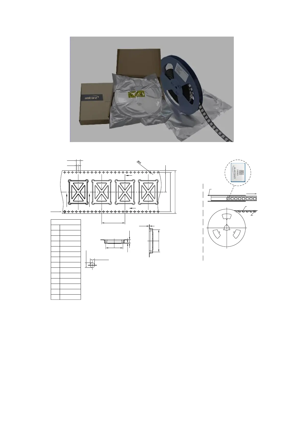
Note:
1. The cumulative tolerance of 10 side holes should not exceed ± 0.2 mm.
2. Material of the tape: Black antistatic PS (surface impedance 10
5
-10
11
)
(surface static voltage <100 V), thickness: 0.35 mm.
3. Total length of the 13-inch reel package: 6.816 m (Length of the first part of
empty packets: 0.408 m, length of packets containing modules: 6 m, length
of the last part of empty packets: 0.408 m).
4. Total number of packets in the 13-inch reel package: 284 (Number of the
first part of empty packets: 17; actual number of modules in the packets:
250; number of the last part of empty packets: 17).
5. All dimension designs are in accordance with EIA-481-C-2003.
6. The maximum bending degree of the carrier tape within the length of 250
mm should not exceed 1 mm (see the figure below).