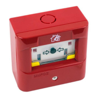
MANUAL CALL POINT
TYPE FD3050
INSTRUCTION MANUAL
GENERAL DESCRIPTION
The manual call point FD3050 is designed for indoor installation as a component of a Conventional Fire Alarm System.
The unit is compatible with the requirements of the European Standard EN54-11:2001/A1:2005.
Unpacking of the manual call point is shown in the sequence of steps: pos.1,2 and 3, Fig. 4 .
п
TECHNICAL DATA
Nominal operating voltage 24 Vdc
Minimum operating voltage 10 Vdc
Maximum operating voltage 30 Vdc
Resistance load Refer Fig.3
and Alarm threshold current.
Electrical Installation Through terminal for connecting
wires with cross-section (0,5-1,5) mm2
Application INDOOR USE, TYPE A (direct operation)
Operational temperature range from minus 10°С to plus 55°С
Relative humidity resistance (93±3)% at 40°С
Dimensions 98х96х51 mm
Weight of the manual call point 0.150 kg
Material ABS
п
INSTALLATION
To install the manual call point, please refer the sequence pos. 1, 2, 3, 4, 5, 6, 7, 8 and 9 of g. 4:
Detailed wiring diagram is shown on g.1. The EOL element is part of the set provided with the conventional FAP,
where the FD3050 is connected to.
The manual call point is able to trigger dry contact, refer wiring diagram g. 2.
п
Alarm threshold current in state of operation (Fire mode) is 60mA when operate with UniPOS conventional line.
If necessary to change the manual call point alarm threshold current, cut the
additional bridges ( g.3).
TESTING
The manual call point is tested as a part of the Conventional Fire Alarm System or on service schedule.
1. Теst procedure
1.1. Power supply the manual call point from the conventional re detection line (10-30V).
1.2. Press the manual call point on the specic place till showing of the two yellow thumb of the actuating member
g 5, pos 2.
1.3. The manual call point is activated - in “Alarm mode”.
2. Reset to duty mode:
To reset the manual call point to duty mode, please refer the sequence pos. 3 and 4 of g. 5
The reset key must be rotate clockwise to retract two yellow thumb
of the actuating member g 5, pos 4.
SERVICE SCHEDULE
1. Inspection for visible physical damage - weekly
2. Trigger on standard operation scenario - monthly
п
WARRANTY
The warranty period is 36 months from the date of purchase.
The manufacturer guarantees the normal operation of the unit providing that the requirements set herein have
been observed.
The manufacturer does not bear warranty liabilities for damages caused through accidental mechanical damage,
misuse, adaptation or modication after production. The manufacturer bears warranty liabilities for damages in the
unit caused through manufacturer's fault only.
Manufacturer: UniPOS Ltd., 47 San Stefano Street, Pleven 5800, Bulgaria, http://www.unipos-bg.com
 Loading...