A
B
Y
X
Z
W
2
4
7
8
5
4
9
4
LN
N
L
N
T
L
N
L
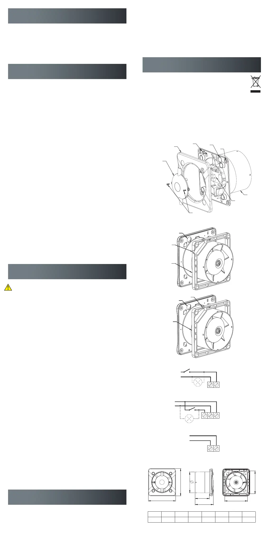
Ref. Ø A B X Y W Z
mm 100 109 109 128 128 88 77
Fig. 3
Fig. 2a
Fig. 1
Fig. 2b
Fig. 6
Fig. 4
Fig. 5
SAFETY INSTRUCTIONS
Area of application and operating conditions
The ventilator is designed to extract normal, non-aggressive air containing small
amounts of dust (normal house dust – particle size 10 μm). It is only designed for
use as part of a fixed indoor installation. The maximum permitted surrounding tem-
perature is 40°C. The ventilator complies with protection class IPX4 and is equipped
with double insulation. It can be installed in locations containing a bath or shower in
accordance with PN-IEC 60363-7-701.
FUNCTIONS
Standard on/off (LM no. 7878101396)
The ventilator is switched on and off by means of a separate switch on the build-
ing’s main power board, either independently or in conjunction with the lighting. To
be connected to the terminal block as shown in Fig. 3.
Timer (LM no. 7878101419)
The ventilator is switched on and off by means of a separate switch on the building’s
main power board, either independently or in conjunction with the lighting. Built-in
timer with infinitely variable, adjustable time stop delay (3-30 min.) You adjust the
time stop delay by turning the timer screw. The time stop delay is calculated from
the time the separate switch is turned off. To be connected to the terminal block as
shown in Fig. 4.
Hygrostat (LM no. 7878101406)
The ventilator is activated automatically based on the detection of relative humidity
(40-90% RF) by the built-in humidity sensor (hygrostat). In addition, it is equipped
with a timer with infinitely variable, adjustable time stop delay (3-30 min.) The
ventilator can be connected to the terminal block in two ways.
Connection as shown in Fig. 4:
Automatic activation by the humidity sensor or manual activation via a separate
switch on the building’s main power board, either independently or in conjunction
with the lighting. After the lighting or the switch has been turned off, the ventilator
continues to run for the duration of the set time stop delay, provided the humidity
value setting on the hygrostat has not been exceeded.
Connection as shown in Fig. 5:
The ventilator is activated automatically when the level of humidity in the air exceeds
the set value on the hygrostat. The ventilator switches off when the level of humidity
has dropped below the set value plus the timer’s set time stop delay.
NOTE: If the green light-emitting diode on the ventilator is lit, the level of humidity
in the room is higher than the set value on the hygrostat. The time stop delay is cal-
culated from the time the green light-emitting diode goes off. If the level of humidity
in the room exceeds 90% RF, the ventilator will run non-stop.
Switch (LM no. 7878101422)
The ventilator is turned on and off manually by pulling the chain switch.
To be connected to the terminal block as shown in Fig. 5.
INSTALLATION
Installation, electrical connection and adjustment may only be carried
out by a certified electrician in accordance with current legislation!
Make sure that the mains voltage has been switched off before com-
mencing work!
• Remove the cover (1) of the ventilator housing (8) by loosening the two screws (6)
• Remove the ventilator’s cover plate (2) (snap fasteners)
• Mark off the holes for the ventilator housing (8) and pre-drill, if necessary
• Run the cable through the hole (4) in the baseplate of the ventilator housing (8)
• Use the provided adapter plate (9) if the ventilator is connected using an exter-
nal wire
• Fasten the ventilator housing (8) by tightening the screws. Use the screws pro-
vided or other suitable screws or plugs depending on the nature of the base
• Strip the insulation on the wires by about 4 mm and connect as shown in Fig. 3-5
• Check that the wires are firmly connected to the terminal block
• Mount the cover plate (2)
• Fasten the cover (1) onto the ventilator housing (8) using the two screws (6)
(only version with standard on/off and switch)
• Check that the ventilator propeller can rotate freely. If the ventilator is fitted with
a back-pressure damper (accessory), check that there is enough space for the
damper to open.
• Mount the front panel (sold separately)
Adjustment (only version with timer and hygrostat)
• Adjust time stop delay and humidity level with the help of the spanner (3) and
the potentiometer is located under the cover (7)
• Fasten the cover (1) onto the ventilator housing (8) using the two screws (6)
• Mount the front panel (sold separately)
NOTE: The following applies to all models: the front panel (sold separately) is part
of the ventilator’s protection against accidental contact and must always be fitted. If
the ventilator is mounted on a wall and connected to a short vertical ventilation duct,
the opening of the duct to the outside must be protected by an air vent grille.
Commissioning
Switch on the power, start the ventilator (automatically or manually) and check
whether it runs smoothly without unusual noise.
Dimensions See Fig. 6.
CLEANING AND MAINTENANCE
Take care to completely disconnect the ventilator from the power supply before
carrying out any form of cleaning, inspection or maintenance. Switch off the fuse
block to which the ventilator is connected on the distribution board and make sure
that it cannot be reconnected unintentionally while the work is being carried out.
• To clean the grille on the front panel of the ventilator simply wipe it from time to
time with a well-wrung wet cloth dipped in a mild detergent
• Never use solvents or aggressive detergents on the ventilator
• Never use water jet or compressed air
• The ventilator’s ball bearings have been lubricated for life and do not require
any maintenance
Unite disclaims all liability for damage caused by incorrect cleaning or maintenance
as well as unauthorised attempts at repairing or modifying the ventilator.
REMOVAL
When your ventilator has reached the end of its useful life, it should not be
discarded together with normal household waste. The crossed-out wheelie
bin symbol indicates that the ventilator constitutes electronic waste which
must be returned to a recycling facility. You can hand in your discarded
ventilator at your local recycling facility or go to your local municipality’s website
for information about other ways to discard it in an environmentally friendly
manner. By discarding it correctly you help protect the environment and preserve
important resources.
 Loading...