Do you have a question about the Unitek BAMOCAR-PG-D3-400/400 and is the answer not in the manual?
Records changes and versions of the manual.
Lists other products offered by the manufacturer.
Guidance for project planning using manuals.
Specifies the hardware and firmware versions covered.
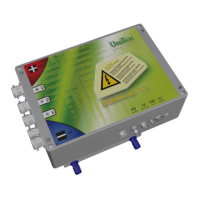
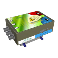
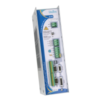
Explains device designations and warning symbols.
Provides an overview of the drive unit's capabilities and applications.
Details the intended applications and technical features.
Outlines important safety rules and precautions for operation.
Instructions and requirements for putting the device into operation.
Provides in-depth explanation of safety measures and requirements.
Defines the proper applications and limitations of the device.
Lists applicable standards and regulations for installation and use.
Identifies potential hazards and residual risks associated with the device.
Presents detailed technical specifications and parameters.
Key considerations before and during mechanical installation.
Provides detailed dimensional drawings for installation.
Instructions for mounting the unit on standard rails.
Instructions for mounting the unit on a flat surface.
Crucial points for safe and correct electrical installation.
Illustrates the internal functional blocks and connections.
Shows the layout and function of all external connectors.
Guidelines for Electromagnetic Compatibility installation and testing.
Detailed pin-out and description for each connector.
Details how to connect the auxiliary power supply.
Explains how to connect power cables for battery and motor.
Specific instructions for connecting the battery.
Details how to connect motor power cables.
Describes the function and connection of digital input signals.
Explains the safety input for enabling and stopping.
Details the function and connection of digital output signals.
Describes the status signalling outputs.
Covers the analogue inputs for setpoints and limits.
States that no analogue output is provided.
Details the RS232 serial communication interface.
Explains the CAN-BUS digital communication interface.
Details the connection for resolver feedback systems.
Covers the connection of TTL incremental encoders.
Details the SIN/COS encoder connection for position feedback.
Explains BL tacho and Hall sensor connections.
Explains the meaning of the device's status indicators.
Lists and explains error codes and their meanings.
Lists and explains warning codes and their meanings.
Shows DC BUS and battery voltage specifications and graphs.
Displays temperature readings from power stage sensors.
| Category | Amplifier |
|---|---|
| Output Power | 160 kW |
| Cooling Method | Liquid Cooled |
| Protection Features | Overcurrent, overtemperature, undervoltage, overvoltage |
| Communication Interface | CAN |
| Input Voltage | 400 VDC |
| Output Current | 400 Arms |
| Efficiency | 98% |