Do you have a question about the Unitek BAMOCAR-PG-D3-700/400 and is the answer not in the manual?
Details the version changes and update dates for the product manual.
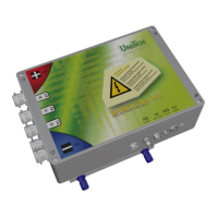
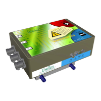
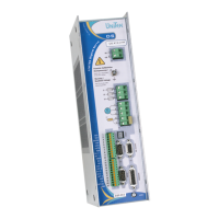
Lists other motor amplifiers and converters offered by UNITEK.
Guides for using BAMOCAR-PG-D3-xxx and NDrive x for project planning.
Specifies the valid hardware and firmware versions for this manual.
Explains device naming conventions and crucial safety warning symbols.
Provides an overview of the drive unit and details on EC, AC, and DC motor concepts.
Details the intended applications, deployment scenarios, structure, and features of the drive unit.
Covers essential safety regulations, high voltage precautions, and safe operating practices.
Outlines commissioning steps, regulatory compliance, and EMC considerations.
Provides in-depth safety information for qualified personnel, working environment, and stress factors.
Defines the correct usage of the device and lists impermissible applications to avoid.
Lists relevant EU standards, directives, and regulations for installation and operation.
Details risks associated with impermissible movements, dangerous temperatures, voltages, and fields.
Presents detailed technical specifications, including electrical data and control signal parameters.
Key considerations before and during mechanical installation, including checks and safety.
Provides detailed physical dimensions and mounting hole references for the device.
Instructions for securely mounting the unit onto standard DIN mounting rails.
Guidance for installing the unit onto a flat mounting surface using appropriate screws.
Essential guidelines for safe and correct electrical connections, including regulations and polarity.
Illustrates the internal functional blocks and signal flow within the device.
Provides a comprehensive diagram showing all external connections and their functions.
Details installation and test conditions for complying with EMC directives and standards.
Details pin configurations for various connectors (X1, X9, X10, X7) including cable information.
Explains how to connect the auxiliary voltage supply (12-24V) and its considerations.
Describes how to connect power cables, including PG cable glands and cable preparation.
Details battery connection requirements, including voltage limits, cross-sections, and pre-charge logic.
Guidance for connecting motor cables, including cable types, cross-sections, and shielding.
Explains the function, connection, and programmability of digital inputs.
Details the safety input RFE and its role in enabling the drive and implementing stop category 0.
Describes the digital outputs, their functions, status, and programmability.
Explains the BTB/RDY signaling contact for operation status and undervoltage monitoring.
Details how to use analog inputs for speed setpoints, current limits, and other functions.
Informs that the BAMOCAR variant does not feature an analogue output.
Explains the meaning of different display states, dot/dash patterns, and NDrive status.
Lists error codes, their meanings, NDrive representation, and addresses for troubleshooting.
Lists warning codes, their meanings, NDrive representation, and addresses for troubleshooting.
Provides data on DC BUS voltage, battery voltage, and overvoltage cut-off levels for 400V and 700V models.
Details temperature readings from power stage sensors and their correlation with current reduction.
| Category | Amplifier |
|---|---|
| Model | BAMOCAR-PG-D3-700/400 |
| Input Voltage | 400 V |
| Efficiency | 98% |
| Protection Features | Overvoltage, Overtemperature, Short Circuit |
| Communication Interface | CAN |