EX-RC1 User Guide
Remote I/O Adapter
The EX-RC1 interfaces between Unitronics Vision OPLCs and remote I/O Expansion Modules distributed
throughout your system.
The adapter is connected to a PLC via CANbus. Each adapter may be connected to up to 8 I/O Expansion
Modules. The network may comprise up to 60 nodes, including both PLCs and adapters; note that the PLC must
comprise a CANbus port. Communication is via UniCAN, Unitronics’ proprietary CANbus protocol.
The EX-RC1 is run by a factory-installed application. The adapter can auto-detect digital I/O Expansion
Modules. If the system includes analog modules, the application must be edited. For more information refer to
the Remote I/O topics in the VisiLogic Help system.
The EX-RC1 may either be snap-mounted
on a DIN rail, or screw-mounted onto a
mounting plate.
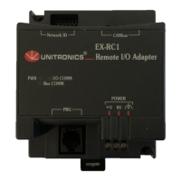
POWER
EX-RC1
0VV
Remote I/O Adapter
PRG
Network ID
CANbus
PWR
I/O COMM.
Bus COMM.
PC to EX-RC1 connection port
Power supply connection points
EX-RC1 to expansion module
connection port
◼ Before using this product, it is the responsibility of the user to read and understand this document and
any accompanying documentation.
◼ All examples and diagrams shown herein are intended to aid understanding, and do not guarantee
operation. Unitronics accepts no responsibility for actual use of this product based on these examples.
◼ Please dispose of this product in accordance with local and national standards and regulations.
◼ Only qualified service personnel should open this device or carry out repairs.
User safety and equipment protection guidelines
This document is intended to aid trained and competent personnel in the installation of this equipment as
defined by the European directives for machinery, low voltage, and EMC. Only a technician or engineer trained
in the local and national electrical standards should perform tasks associated with the device’s electrical wiring.
Symbols are used to highlight
information relating to the user’s
personal safety and equipment
protection throughout this document.
When these symbols appear, the
associated information must be read
carefully and understood fully.
The identified danger causes physical
and property damage.
The identified danger can cause
physical and property damage.
◼ Failure to comply with appropriate safety guidelines can result in severe personal injury or
property damage. Always exercise proper caution when working with electrical equipment.
◼ Check the user program before running it.
◼ Do not attempt to use this device with parameters that exceed permissible levels.
◼ Install an external circuit breaker and take appropriate safety measures against short-circuiting
in external wiring.
◼ To avoid damaging the system, do not connect / disconnect the device when the power is on.