EasyManua.ls Logo

Unitronics EX-RC1 - User Manual

Unitronics EX-RC1
8 pages
Print Icon
To Next Page IconTo Next Page
Loading...
Unitronics
1
EX-RC1 Remote I/O Adapter
The EX-RC1 interfaces between Unitronics Vision OPLCs and remote I/O Expansion Modules distributed
throughout your system.
The adapter is connected to a PLC via CANbus. Each adapter may be connected to up to 8 I/O Expansion
Modules. The network may comprise up to 60 nodes, including both PLCs and adapters; note that the PLC
must comprise a CANbus port. Communication is via UniCAN, Unitronics’ proprietary CANbus protocol.
The EX-RC1 is run by a factory-installed application. For more information refer to the Remote I/O topics in
the VisiLogic Help system.
The EX-RC1 may either be snap-mounted
on a DIN rail, or screw-mounted onto a
mounting plate.
POWER
EX-RC1
0VV
Remote I/O Adapter
PRG
Network ID
CANbus
PWR
I/O COMM.
Bus COMM.
Component identification
1 Status indicators
2 PC to EX-RC1 connection port
3 Power supply connection points
4 EX-RC1 to expansion module
connection port
5 CANbus port
6 DIP Switches
Before using this product, it is the responsibility of the user to read and understand this document and
any
accompanying documentation.
All examples and diagrams shown herein are intended to aid understanding, and do not guarant
ee
ope
ration. Unitronics accepts no responsibility for actual use of this product based on these examples.
Please dispose of this product in accordance with local and national standards and regulations.
Only qualified service personnel should open this device or carry out repairs.
User safety and equipment protection guidelines
This document is intended to aid trained and competent personnel in the installation of this equipment as
defined by the European directives for machinery, low voltage, and EMC. Only a technician or engineer trained
in the local and national electrical standards should perform tasks associated with the device’s electrical wiring.
Symbols are used to highlight
information relating to the user’s
personal safety and equipment
protection throughout this document.
When these symbols appear, the
associated information must be read
carefully and understood fully.
Symbol Meaning Description
Danger
The identified danger causes physical
and property damage.
Warning
The identified danger can cause
physical and property damage.
Caution Caution Use caution.

Other manuals for Unitronics EX-RC1

Question and Answer IconNeed help?

Do you have a question about the Unitronics EX-RC1 and is the answer not in the manual?

Unitronics EX-RC1 Specifications

General IconGeneral
BrandUnitronics
ModelEX-RC1
CategoryAdapter
LanguageEnglish

Summary

User Safety and Equipment Protection Guidelines

Component Identification

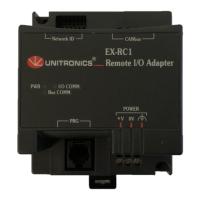
Identifies the physical components of the EX-RC1 adapter, including status indicators and connection ports.

General Safety Warnings

Environmental Considerations

Guidelines for installing the EX-RC1 in suitable environmental conditions, avoiding dust, moisture, and extreme temperatures.

Mounting the Module

DIN-rail Mounting

Steps for mounting the EX-RC1 adapter onto a standard DIN rail using its snap-on mechanism.

Screw-Mounting

Setting the Unit ID Number

Connecting Expansion Modules

Wiring Safety Precautions

Safety guidelines related to wiring the EX-RC1 and expansion modules, emphasizing caution with live wires.

Wiring Procedures

Wiring Power Supply

Instructions for connecting the power supply to the EX-RC1 adapter, including earthing recommendations.

Communication

Connecting EX-RC1 to a PC

Guide on connecting the EX-RC1 adapter to a PC via a programming cable, detailing the RS232 port pinout.

Connecting EX-RC1 to CANbus Network

How to connect the EX-RC1 adapter to an OPLC using the CANbus protocol, highlighting galvanic isolation.

CANbus Wiring

Details on CANbus network wiring, including terminators, grounding, and cable type recommendations.

Network Layout

EX-RC1 Technical Specifications

I;O Module Capacity

Specifies the maximum number of I/O modules connectable to the EX-RC1 adapter.

Power Supply Specifications

Details on the power requirements, permissible range, and current for the EX-RC1.

Status Indicators

Explains the meaning and behavior of the status LEDs on the EX-RC1 for power and communication.

Communication Interface Specifications

Technical details for RS232 and CANbus communication interfaces, including voltage limits and cable types.

Environmental Specifications

Environmental operating conditions such as temperature range, storage temperature, and humidity.

Mounting Options

Describes the available mounting methods for the EX-RC1, including DIN-rail and screw-mounting.

Related product manuals