EX-RC1 Remote I/O Adapter 2/12
6
Unitronics
Communication
Connecting the EX-RC1 to a PC
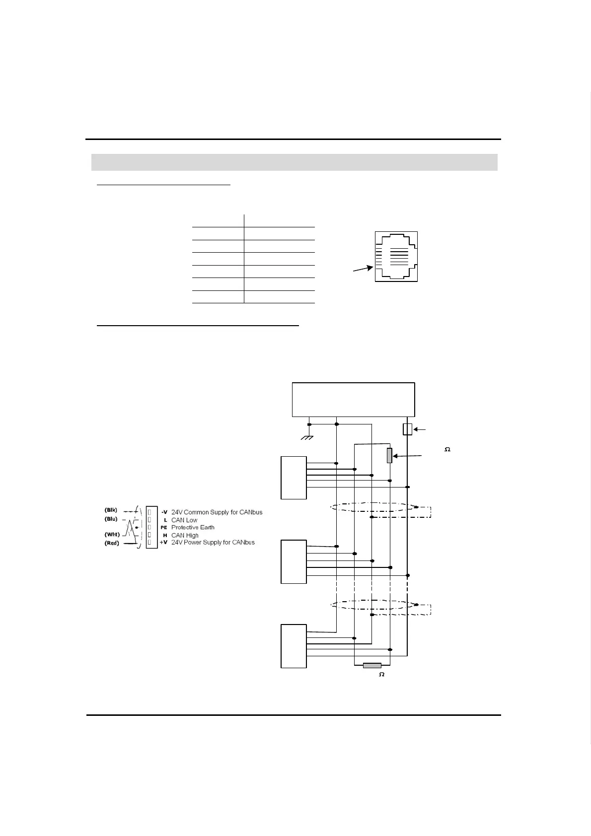
Connect the PC to the adapter via the programming cable. The pinout below shows the RS232 port signals.
Pin # Description
Pin #1
1 —
2 0V reference
3 TXD signal
4 RXD signal
5 0V reference
6 —
Connecting the EX-RC1 to the CANbus network
Connect the EX-RC1 adapter to an OPLC as shown below. The module communicates via Unitronics’
proprietary UniCAN protocol. UniCAN can comprise up to 60 nodes, including PLCs and EX-RC1
remote I/O adapters.
The CANbus port is galvanically isolated.
CANbus Wiring
121
terminating
Circ uit
protection
device
24V Power
Supply
PE
-V
L
-V
H
Network terminators: Place terminators
at each end of the CANbus network.
Resistance must be set to 1%, 121O,
1/4W.
Connect ground signal to the earth at
only one point, near the power supply.
The network power supply need not be
at the end of the network.
CANbus Connector