10. Close (A) Low Side and (B) High Side manifold valves.
11. Disconnect (C) Blue EZ Turn Hose from refrigerant cylinder.
12. Disconnect (E) Red EZ Turn Hose from (C) Blue Hose EZ Access “T” tting.
13. The hoses have now been purged of non-condensable gases with the
refrigerant needed for service.
USER MANUAL - PART# USMAN5
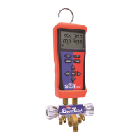
Uniweld SmarTech Wireless Digital Manifold
FOR USE BY PROFESSIONALS. This manifold is designed for use by technically
trained refrigeration and air conditioning service technicians, due to the
unusually HIGH PRESSURE AND HAZARDOUS GASES IN ALL SYSTEMS,
misapplication could result in injury or death. The manufacturer warns
against the sale of this product to, or its use by, other than professional
trained personnel.
WARNING: Read carefully and completely before using equipment.
Keep for reference and store in back of protective case.
WARNING: Always wear safety goggles when working with refrigerants.
WARNING: CALIFORNIA PROPOSITION 65: This product contains chemicals
known to the State of California to cause cancer and birth defects or other
reproductive harm
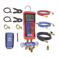
Package Contents
1. SmarTech Wireless Digital Manifold w/ Rubber Boot
2. (1) Blue and (1) Red Temperature Clamp K-Type with 6 Ft. lead
3. (2) Thermocouple Bead Probes K-Type
4. (1) Red 5 Ft. EZ Turn® Anti-Blowback Hose
5. (1) Blue 5 Ft. EZ Turn® Anti-Blowback Hose with 1/4” EZ Access “T” Fitting™
6. (1) Black 5 Ft. Fast-Flo 3/8” Vacuum & Charging Hose with Ball Valve
7. (1) Adaptor 3/8” MF x 1/4” FF
8. SmarTech Protective Padded Case
9. (6) AA Batteries (not shown)
10. (10) Velcro Cable Tie Straps
OI0047
The SmarTech Digital Manifold is extremely accurate and can be used to pressure
test the hoses and manifold valves for leaks. Note: The POE oil used in R410A is very
aggressive and causes the rubber seals in the hoses and manifold valve stems to
wear rapidly; they may need replacing every couple of months depending on usage.
It is recommended to check your manifold and hoses regularly for leaks due to
normal wear on rubber gaskets and seats.
1. Connect (C) Blue EZ Turn Hose to manifold 45º hose holder tting.
2. Connect (E) Red EZ Turn Hose to manifold 45º hose holder tting.
3. Connect (D) Black 3/8” Hose with Ball Valve open to nitrogen regulator
using the 3/8”x1/4” adaptor.
4. Open (A) Low Side and (B) High Side manifold valves.
5. Open nitrogen tank valve and set delivery pressure between 400 to 500 psi.
6. Close (D) Black 3/8” Hose Ball Valve. A slight pressure drop is normal as the hoses
stretch under pressure but will stabilize after a couple of minutes.
7. Close (A) Low Side and (B) High Side manifold valves.
8. If digital pressure readings are stable the hoses and manifold are
functioning properly.
9. If the pressure reading continues to decrease there is a leak in the hoses or
manifold that must be repaired. Determine origin of the leak and replace
the gaskets and O-rings as needed. Repeat pressure test.
Manifold and Hoses Leak Test
Prior to purging the hoses with the refrigerant needed for service it may be
necessary to discharge unwanted refrigerant or nitrogen from the hoses.
1. Open (A) Low Side and (B) High Side manifold valves.
2. Aim the (D) Black 3/8” Hose Ball Valve in a safe direction and open
the ball valve to discharge the unwanted refrigerant or nitrogen from the hoses.
3. The digital pressure readings for both Hi and Lo should read zero before
continuing to the next step of purging the hoses with refrigerant.
4. Connect (E) Red EZ Turn Hose to (T) Blue Hose EZ Access “T” tting.
5. Connect (C) Blue EZ Turn Hose to refrigerant cylinder.
6. Close (D) Black 3/8” Hose Ball Valve.
7. Open refrigerant cylinder valve.
8. Aim the (D) Black 3/8” Hose Ball Valve in a safe direction, open ball valve
and begin purging non-condensable gases.
9. Close (D) Black 3/8” Hose Ball Valve when all non-condensable gases have
been purged.
The SmarTech Digital Manifold is extremely accurate and can be used to
pressure test the system for leaks. Prior to pressure testing with nitrogen it
may be necessary to discharge unwanted refrigerant from the hoses.
1. Open (A) Low Side and (B) High Side manifold valves.
2. Aim the (D) Black 3/8” Hose Ball Valve in a safe direction and open
the ball valve to discharge the unwanted refrigerant from the hoses.
3. The digital pressure readings for both Hi and Lo should read
zero before continuing to the next step.
4. Connect (E) Red EZ Turn Hose to (F) High Side service tting.
5. Connect (C) Blue EZ Turn Hose to (G) Low Side service tting.
6. Connect (D) Black 3/8” Hose with Ball Valve open to nitrogen regulator
using the 3/8”x1/4” adaptor.
7. Open nitrogen tank valve and set delivery pressure to system manufacturer’s
recommended test pressure.
8. Close (D) Black 3/8” Hose Ball Valve. A slight pressure drop is normal as the
hoses stretch under pressure but will stabilize after a couple of minutes.
9. Close (A) Low Side and (B) High Side manifold valves.
10. If after a few minutes the pressure reading continues to decrease there
is a system leak. The leak must be repaired then repeat the system
pressure test.
11. If after a few minutes the digital pressure readings are stable the system is
leak-free.
12. Close the nitrogen cylinder valve.
13. Disconnect (D) Black 3/8” Hose from the nitrogen regulator.
14. Open (A) Low Side and (B) High Side manifold valves.
15. Aim the (D) Black 3/8” Hose Ball Valve in a safe direction and open
the ball valve to discharge the nitrogen from the system and hoses.
16. Proceed with evacuating the system.
Prior to charging a system with refrigerant the hoses must be evacuated or purged with
the refrigerant needed for service, see Discharge and Purge Hoses before proceeding.
1. Turn system o and connect (E) Red EZ Turn Hose to (F) High Side service tting.
2. Attach (H) Red Temperature Clamp to (F) High Side copper tubing.
3. Connect (C) Blue EZ Turn Hose to (G) Low Side service tting.
4. Attach (J) Blue Temperature Clamp to (G) Low Side copper tubing.
5. Connect (D) Black 3/8” Hose with Ball Valve closed to refrigerant cylinder.
6. If this is a new system installation, open (F) High Side and (G) Low Side
condenser service valves.
7.
Open (D) Black 3/8” Hose with Ball Valve and refrigerant cylinder valve.
8. Turn system on; SmarTech Superheat and Subcooling features can be used at this time
to properly charge the system for maximum eciency and optimal performance.
9. To add refrigerant open (A) Low Side manifold valve.
10. Close (A) Low Side manifold valve and let the system temperatures and pressures
stabilize. Check Superheat and Subcooling “Smart Charge Zone”, if additional
refrigerant is needed repeat steps 9 and 10 until the “Smart Charge Zone” is “Green” .
11.
Close (A) Low Side manifold valve when desired amount of refrigerant has
been added.
12. Close (D) Black 3/8” Hose Ball Valve and refrigerant cylinder valve.
13. Disconnect (D) Black 3/8” Hose with Ball Valve from refrigerant cylinder and
connect to manifold hose holder tting.
14. Disconnect (E) Red EZ Turn Hose and (C) Blue EZ Turn Hose from system and
connect to manifold hose holder ttings.
Prior to evacuating the system it may be necessary to discharge unwanted
nitrogen or refrigerant from the hoses, see Discharge & Purge Hoses steps 1-2
before proceeding.
1. Connect (E) Red EZ Turn Hose to (F) High Side service tting.
2. Connect (C) Blue EZ Turn Hose to (G) Low Side service tting.
3. Optional: Connect (Uniweld Part# UVG) Digital Vacuum Gauge
to (T) Blue Hose EZ Access “T” tting.
4. Open (A) Low Side and (B) High Side manifold valves.
5. Connect (D) Black 3/8” Hose with Ball Valve open to vacuum pump.
6. Evacuate system according to manufacturer’s specication.
7. Close (A) Low Side and (B) High Side manifold valves.
8. Close (D) Black 3/8” Hose Ball Valve and disconnect from the vacuum pump.
9. Turn vacuum pump o and proceed with charging system with refrigerant.
A
A
C
T
C
E
E
A
B
B
B
D
D
MENU PAIR
O
Enter
Right
––––
Hold
Left
––––
Max Min
Down
––––
–
Up
––––
+
Digital Manifold
A
C
E
D
B
LOW
HIGH
MENU PAIR
O
Enter
Right
––––
Hold
Left
––––
Max Min
Down
––––
–
Up
––––
+
Digital Manifold
A
J
H
C
G
E
D
B
F
LOW
HIGH
NITROGEN
NITROGEN
REFRIGERANT
REFRIGERANT
VACUUM
Figure 2
Figure 3
Figure 1
MENU PAIR
O
Enter
Right
––––
Hold
Left
––––
Max Min
Down
––––
–
Up
––––
+
Digital Manifold
A
C
T
E
D
B
LOW
HIGH
CLOSED
T
T
T
Multi-function ¼”
Male Flare “T” Fitting
built into the blue hose
for Simplied
Purging and Charging
Refrigerant.
EZ Access “T” Fitting™
OPEN
Discharge and Purge Hoses
Discharge and Purge Hoses
Pressure Test System
Evacuating System
Charging System
See Figure 1
See Figure 2
See Figure 3
See Figure 3
See Figure 3
A
A
C
E
B
B
D
D
D
A
B
D
D
A
A
A
A
A
C
J
T
C
C
G
G
G
G
E
H
E
E
F
F
F
F
G
F
B
B
D
D
D
D
D
D
A
C
T
E
B
D
D
D
D