Step 3
After all components from Step 2 are in place, you may choose
to tighten the set screws, which will lock all the components to-
gether, and prevent them from separating or drifting on their own.
They are located at each insertion point, and marked in this in-
struction book with a “ ”.
• At the top of the Base’s neck, where the Gas arm is inserted.
• At the top of the Gas arm, where the Extension arm is inserted.
• And at the end of the Extension arm, where the Monitor joint is
inserted.
Use the 3 mm Allen wrench provided. Make sure not to overtight-
en the set screws.
*
*
*
*
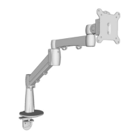
Step 2
With the Base attached to the desk, it’s time to assemble the re-
mainder of the arm by inserting the Gas arm, which ships with a
pre-installed stopping pin at the bottom near the post (see g.
4). This pin limits the arm’s rotation to 180 degrees. If you want
a full 360 degrees of rotation, remove this pin with the 2 mm
Allen wrench. Then insert the Gas arm into the Base.
Insert the Extension arm into the Gas arm, and complete this
part of the assembly by inserting the Monitor joint into the Ex-
tension Arm.
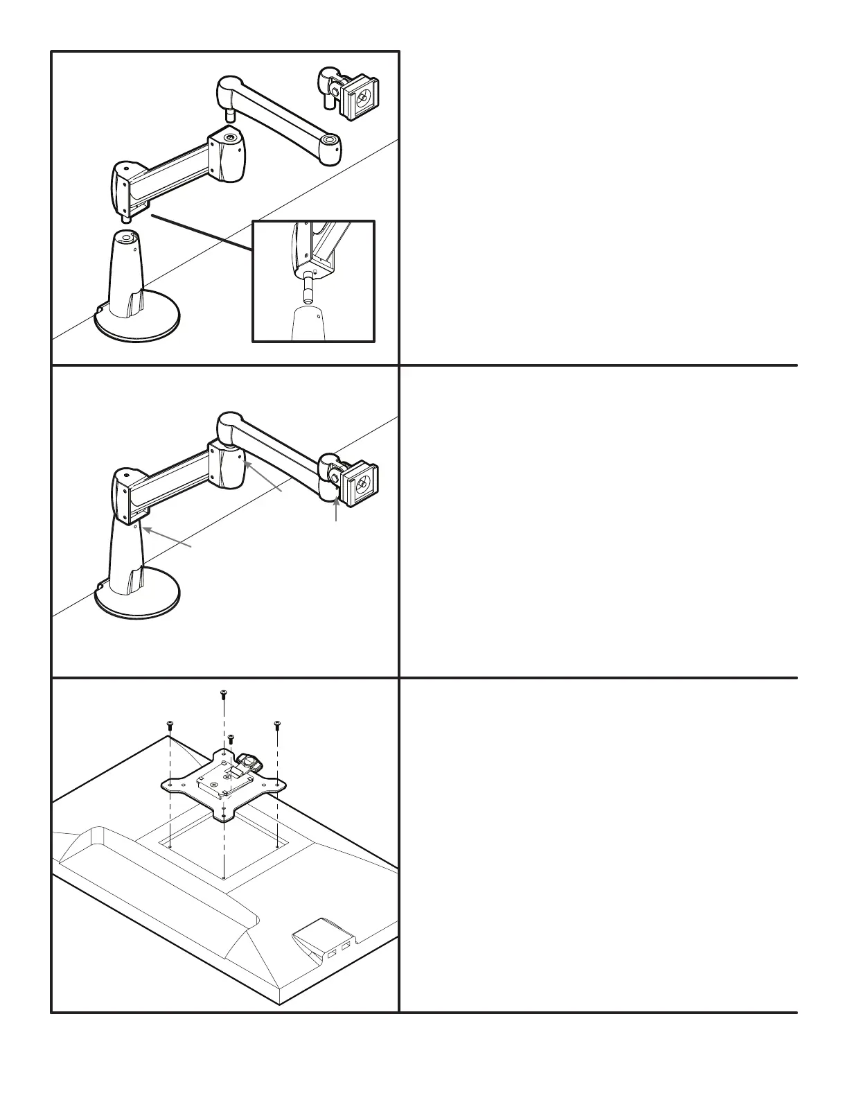
Step 4
Place your monitor face down on a at surface, making sure
not to scratch the screen. Next, attach the VESA mount to
the back of your monitor using a Phillips-head screwdriver
and four Monitor screws. The mount is designed to t the in-
dustry standard VESA 75 mm & 100 mm hole patterns. Make
sure the VESA mount is securely fastened to your monitor
before moving on to the next step.
Note: make sure the tab on the VESA mount is facing the top
of your monitor.
© UPLIFT Desk • 1-800-349-3839 • info@upliftdesk.com • upliftdesk.com
g. 4
 Loading...