Hot Switch
Power Source
3-Way
Timer
Restore power supply at the circuit breaker or fuse.
8
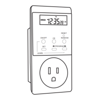
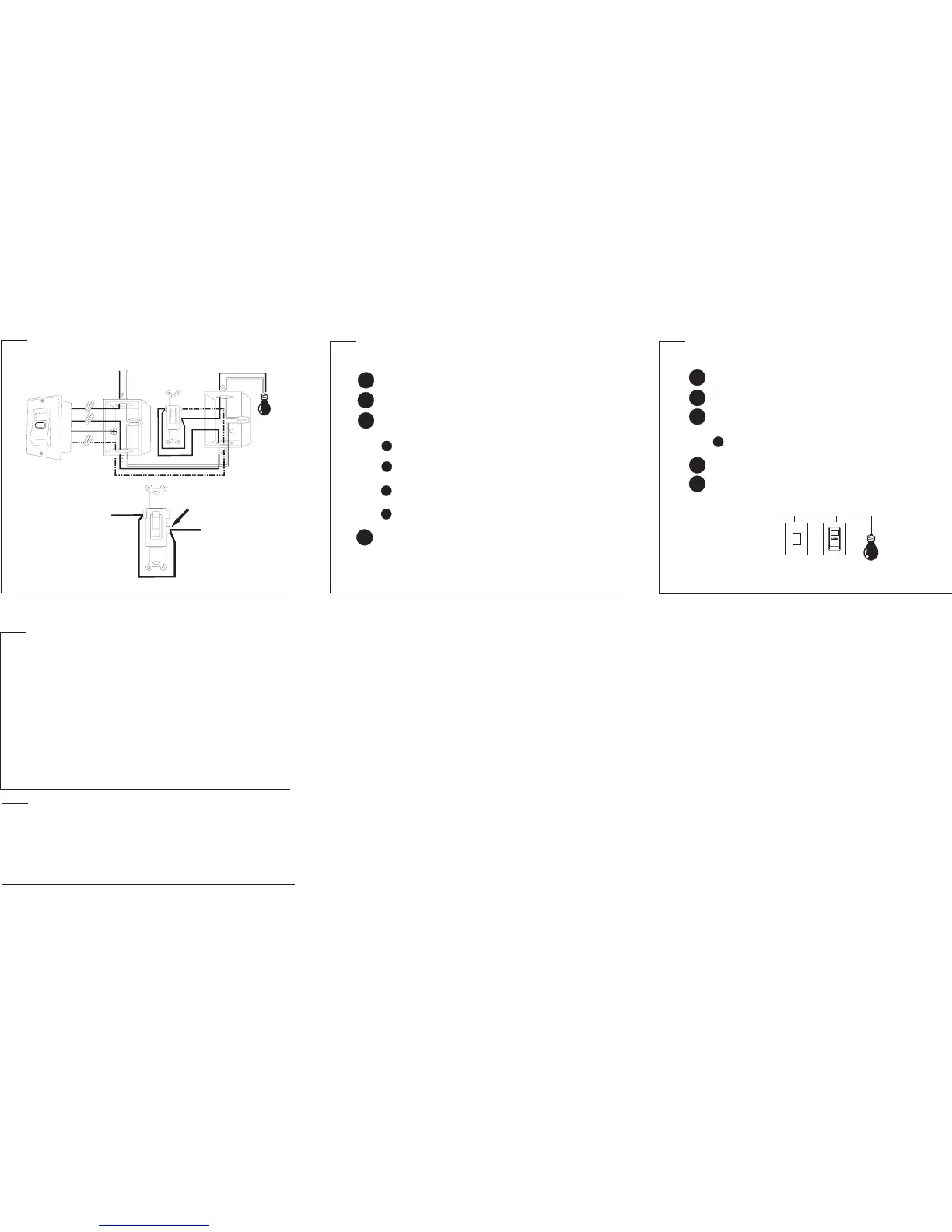
THREE-WAY INSTALLATION
ADDING A JUMPER WIRE TO THE HOT SWITCH
*
Disconnect the power supply at the circuit breaker or fuse before
proceeding with the installation.
5
Take out the HOT switch and identify the terminal.common
6
Connect the wire to the HOT switch according to diagram
FIGURE 3.
jumper
Connect the wire from the terminal to the
terminal of the HOT switch.
jumper common
hot
Mount HOT switch back into the wall box carefully.
7
TROUBLESHOOTING
LCD display seems “frozen”.
Buttons won’t respond.
Programmed ON/OFF times
don’t execute.
Programmed ON/OFF times
don’t execute at specified times.
Three-way switch is not working
properly.
Press reset button to reset timer.
Ensure that the program disable
feature is not enabled.
Ensure that the random function
is not enabled.
Disconnect power supply at the
circuit breaker or fuse. Check
installation for proper wiring.
problem solution
TECHNICAL SPECIFICATIONS
Program: 20 programs
Ratings: 120V AC
Max Load: 500W; single pole or three-way
Min switching time: 1 minute
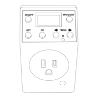
INSTALLING THE TIMER IN PLACE OF HOT SWITCH
THREE-WAY INSTALLATION DIAGRAM
THREE-WAY INSTALLATION
1
2
Remove existing switch and identify the wires in the wall box.
Using the supplied wire nuts, securely fasten the wires on the timer
to the wires in the wall box according to diagram FIGURE 3.
3
Disconnect the power supply at the circuit breaker or fuse before
proceeding with the installation.
Connect one of the (hot) wire on the timer to the
wire in the wall box coming from the lighting fixture.
black hot
Connect the other (hot) wire on the timer to the wire
in the wall box coming from the HOT switch.
black hot
Connect the (three-way) wire on the timer to the
wire in the wall box coming from the HOT switch.
red three-way
Mount timer into the wall box carefully.
4
INSTALLING THE TIMER IN PLACE OF LOAD SWITCH
For proper grounding, connect the (ground) wire on
the timer to the ground “screw” found inside the wall box.
green
JUMPER WIRE
COMMON TERMINAL
HOT WIRE
HOT WIRE
FIGURE 2
CLOSE UP VIEW OF THE LOAD SWITCH
Red
ETW193
JUMPER
3Way
Black
Black
Power Source
LOAD
COMMON
Green
LOAD SWITCH
PAGE 7 PAGE 8 PAGE 9
PAGE 16
 Loading...