EasyManua.ls Logo

UPOWER Ecoline UE-48LI3750I - User Manual

UPOWER Ecoline UE-48LI3750I
24 pages
Print Icon
To Next Page IconTo Next Page
Loading...
UE-48LI3750I ESS Unit
User Manual
Question and Answer IconNeed help?

Do you have a question about the UPOWER Ecoline UE-48LI3750I and is the answer not in the manual?

Summary

Safety Precautions

Preface

Manual declaration

Provides a manual declaration for the UE-48L137501 ESS Unit.

1 Introduction

1.1 Brief Introduction

Provides a concise overview of the UE-48L137501 ESS unit's purpose and applications.

1.2 Product Properties

Details the key features and advantages of the UE-48L137501 energy storage product.

1.3 Product identity definition

Explains the product's identification, including model, capacity, and specifications, via its nameplate.

2 Product Specification

2.1 Size and Weight

Presents the physical dimensions and weight of the UE-48L137501 ESS unit.

2.2 Performance Parameter

Lists the technical performance metrics such as voltage, capacity, power, and currents.

2.3 Interface Definition

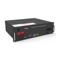
Describes the various interfaces and ports available on the front of the battery module.

2.3.1 DIP switch definition and description

Explains the function and configuration of the DIP switches for communication protocol and baud rate selection.

2.4 Battery Management System(BMS)

Details the Battery Management System (BMS) functions and protections.

2.4.1 Voltage Protection

Details the low and over-voltage protection mechanisms during discharge and charging.

2.4.2 Current Protection

Covers the over-current protection modes activated during charging and discharging.

2.4.3 Temperature Protection

Explains the temperature protection features that prevent operation outside safe temperature ranges.

2.4.4 Other Protection

Describes additional protection features like short circuit protection and self-shutdown.

3 Installation and Configuration

3.1 Preparation for installation

Outlines safety requirements, environmental conditions, and necessary tools for installation.

3.1.1 Environmental requirements

Specifies the required environmental conditions for optimal battery operation and longevity.

3.1.2 Tools and data

Lists the hardware tools and meters recommended for the installation process.

3.2 Equipment installation

Provides a step-by-step guide for the mechanical and electrical installation of the battery system.

3.2.1 Installation preparation

Details the initial steps for preparing the equipment and tools before mechanical installation.

3.2.2 Mechanical installation

Guides through the physical mounting and securing of the battery unit in the cabinet or bracket.

3.2.3 Electrical installation

Covers the procedures for connecting power cables and ensuring proper electrical connections.

3.2.4 Battery parameter settings on the inverter

Explains how to configure the inverter with the correct battery parameters for optimal performance.

4 Use, maintenance and troubleshooting

4.1 Battery system usage and operation instructions

Guides users on how to safely start up and operate the battery system after installation.

4.2 Alarm description and processing

Explains various alarm indications, their categories, and the recommended processing steps.

4.3 Analysis and treatment of common faults

Provides a table to help diagnose and resolve common issues encountered with the battery system.

Overview

The UE-48LI3750I ESS Unit is a lithium iron phosphate battery energy storage system designed to provide energy storage for photovoltaic power generation users through parallel combination. It can store excess electricity from a photovoltaic power generation system during the day and supply stable power to user equipment as a power backup at night or when needed. This system aims to improve the efficiency of photovoltaic power generation and increase electric power efficiency through peak load shifting.

Function Description:

The UE-48LI3750I functions as a standard battery system unit. Users can connect multiple UE-48LI3750I units in parallel to form a larger capacity battery pack, meeting long-term power supply needs. It is particularly suitable for energy storage applications characterized by high operating temperatures, limited installation space, long power backup times, and extended service life. The system's positive electrode materials are lithium iron phosphate (LiFePO4), which contributes to its safety and longer lifespan. A Battery Management System (BMS) effectively manages the battery cells, providing protection functions such as over-discharge, over-charge, over-current, and abnormal temperature. The unit features self-management for charging and discharging, including single-core balancing. Its intelligent design incorporates an integrated inspection module. Flexible configurations allow for parallel connection of multiple batteries to achieve longer standby times. The system operates with self-ventilation, resulting in lower system noise. It exhibits less battery self-discharge, allowing for a recharging period of up to 10 months during storage. The battery has no memory effect, enabling shallow charging and discharging.

Important Technical Specifications:

  • Module Type: LFP Lithium Ion Battery
  • Model: UE-48LI3750I
  • Capacity/Voltage: 75Ah/48V
  • Total Storing Energy: 3.6kWh
  • Charge Voltage: 53.5V
  • Max. Discharge Power: 2.4kW
  • Nominal Voltage: 48V
  • Work Voltage Range: 42-54V
  • Nominal Capacity: 75Ah
  • Nominal Energy: 3.6kWh
  • Nominal Power: 1.8kW
  • Max Power: 2.4kW
  • 1S Peak Power: 2.64kW
  • 1S Peak Current: 55A
  • Charging Current: 37.5A
  • Discharge Current: 37.5A
  • Dimensions: 480×360×130mm
  • Weight: ≈31kg
  • Working Temperature: -20°C to +55°C (Charging temperature range: 0°C to +55°C; Discharging temperature range: -20°C to +55°C)
  • Storage Temperature: -10°C to +35°C
  • Relative Humidity: 5% to 85%RH
  • Elevation: No more than 4000m

Usage Features:

The device is designed for indoor installation, avoiding direct sun, wind, conductive dust, and corrosive gas. The installation location should be away from the sea to prevent brine and high humidity. The ground for product arrangement must be flat and level, with no flammable or explosive materials nearby. The optimal ambient temperature for operation is 15°C to 30°C. The front panel includes a Power switch (OFF/ON) which must be in the "ON" state during use. A Ground connection point ensures proper grounding. Positive and Negative sockets are for battery output connections. A SW (battery wake/sleep switch) allows users to power on or off the battery by pressing and holding for 3 seconds when the OFF/ON switch is in the ON state. SOC (State of Charge) indicators, represented by green lights, show the remaining battery power. An ALM (Alarm) indicator flashes red for alarms and stays solid red during protection status. A RUN indicator flashes green during standby and charging, and stays solid green during discharging. CAN/485 ports are for communication cascade, supporting CAN/RS485 communication (factory default is CAN). A DRY CONTACT port is also available. An ADD DIP switch is used for configuration, particularly when batteries are connected in parallel.

DIP Switch Configuration:

The DIP switches define communication protocols and baud rates.

  • #1 & #2: Define different protocols and distinguish between master and slave units.
  • #3 & #4: Select baud rate (OFF: CAN: 500K, 485: 9600; ON: CAN: 250K, 485: 115200). When multiple batteries are connected in parallel, the master unit communicates with slave units via the CAN interface. The master then aggregates information from the entire battery system and communicates with the inverter via CAN or 485. Specific DIP switch settings are required for compatibility with various inverter brands (e.g., GOODWE, Solis, LUX, Sofar, DEYE, VICTRON, IMEON, Sungrow, SMA, RENAC, DELIOS, SAJ for CAN communication; Axpert-king/VMIII/MAX, Infinisolar, Growatt SPH/SPA for CAN communication; Growatt SPF HVM-P/ES/WPV for RS485 communication; Schneider Conext Series; and ICC for 485 communication). For a single UE-48LI3750I unit, it acts as the master.

Battery Management System (BMS) Protections:

  • Low Voltage Protection (Discharging): Activates when any cell or total voltage drops below a rated value during discharge, triggering an alarm and stopping power supply. Protection clears when voltage returns to the rated range.
  • Over Voltage Protection (Charging): Activates when total voltage or any cell voltage reaches a rated value during charging, stopping the charging process. Protection clears when voltage returns to the rated range.
  • Over Current Protection (Charging): Limits current to 4A if charge current exceeds 45A. Protection is removed after a 10-second delay.
  • Over Current Protection (Discharging): Triggers an alarm and stops discharging if discharge current exceeds the protection value. Protection clears after a rated time delay.
  • Low/Over Temperature Protection (Charging): Stops charging if battery temperature is outside the -5°C to +55°C range. Protection clears when temperature returns to the rated working range.
  • Low/Over Temperature Protection (Discharging): Stops power supply if battery temperature is outside the -20°C to +55°C range. Protection clears when temperature returns to the rated working range.
  • Short Circuit Protection: Activates for 60 seconds if a short circuit occurs when the battery is activated from shutdown.
  • Self-Shutdown: The device enters dormant standby automatically if no external loads, power supply, or communication are connected for over 72 hours.

Installation Procedure:

  1. Preparation: Ensure the ON/OFF switch is "OFF". Determine battery placement, install battery modules mechanically (either on a bracket in a cabinet or using simple brackets).
  2. Electrical Installation: Install ground cable, parallel battery cables, and parallel communication cables.
  3. Self-Test: Turn ON the ON/OFF switch, press the SW button for 3 seconds to wake up the battery. Check system output voltage and LED status. Shut down the system.
  4. Inverter Connection: Connect positive and negative cables from the battery system to the inverter. Connect the communication cable from the master CAN IN port to the inverter. Turn on the Power switch and wake up the system via the SW button. Close the DC breaker between the inverter and battery. Turn on the inverter and verify communication.

Maintenance Features:

  • Long-term Storage: The battery should be recharged once every 6 months, with the charge exceeding 80% of the rated capacity.
  • Discharge Recovery: Charge the battery within 18 hours after it fully discharges or activates over-discharging protection.
  • Troubleshooting: The manual provides a detailed alarm description and processing guide for various fault conditions (e.g., over-current, high temperature, total voltage undervoltage, cell voltage undervoltage). It also offers analysis and treatment for common faults such as no response after power-on, no DC output, short DC power supply time, inability to fully charge, and power cable short-circuit.
  • Safety: Users are warned not to disassemble or repair the device, avoid physical damage, and shut off power before removing or reconnecting wires. Dry powder extinguishers are recommended for fire hazards. Maintenance must be performed by authorized technical personnel.
  • Compatibility: The maximum discharging current of the battery should exceed the load's maximum working current. The manual emphasizes checking compatibility with inverter brands and referring to the latest compatibility document.
  • Circuit Breaker: It is recommended to add a circuit breaker between the inverter and the battery system, with specific voltage (U>60V) and current (I = Inverter power / 45V) requirements.

UPOWER Ecoline UE-48LI3750I Specifications

General IconGeneral
BrandUPOWER Ecoline
ModelUE-48LI3750I
CategoryBattery Pack
LanguageEnglish