38
5 Truck components adjustment and servicing (brief description)
5.1 Engine
Description of engine design as well as instructions for engine operation and mainte-
nance are given in the Operation Manual issued by the Yaroslavl Motor Works.
5.1.1 Fuel system
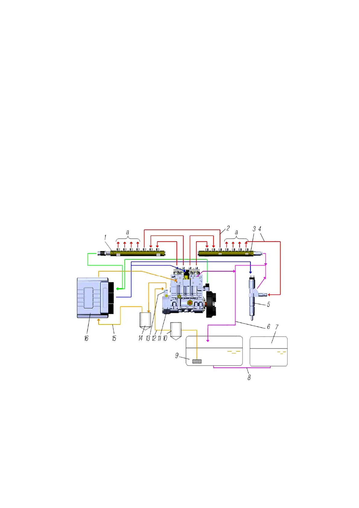
5.1.1.1 Engine Fuel System. Fuel is taken from main fuel tank 9 (Fig. 21) by fuel feed
pump 13 and is supplied to high-pressure fuel pump (HPFP) 11 via coarse-mesh filter 10 and fine-
mesh filter 14. The fuel pump delivers fuel under pressure to accumulators 1 and 3 (ramp) and
then to the nozzles which inject fuel into engine cylinders. The injection is controlled by the en-
gine EDC. Excessive fuel together with air which has entered the system is returned via piping 6
to the fuel tank.
The fuel volume in the main fuel tank is measured by an electrical level gauge installed
in the tank and is controlled by the indicator on the dashboard. The fuel level sensor in the auxilia-
ry fuel tank depends on vehicle modification. In case the fuel level sensor is installed on the auxil-
iary fuel tank, there is a fuel level indicator switch in the cabin.
The main fuel tank is on the left frame sidemember, the auxiliary fuel tank is on the right
frame sidemember.
1,3-high-pressure accumulator; 2,4- high-pressure fuel pipes; 5-injector; 6-drain line fuel pipes; 7-auxiliary
fuel tank; 8-connecting fuel line; 9-main fuel tank; 10-coarse filter; 11-high-pressure fuel pump (HPFP);
12,15-low-pressure fuel lines; 13-low-pressure fuel pump; 14-fine-mesh fuel filter; 16-electronic control
unit; а-fuel lines to injectors
Fig. 21 - Engine Fuel Feed System Diagram
 Loading...