U
SB 7706
Compressor Dual Channel
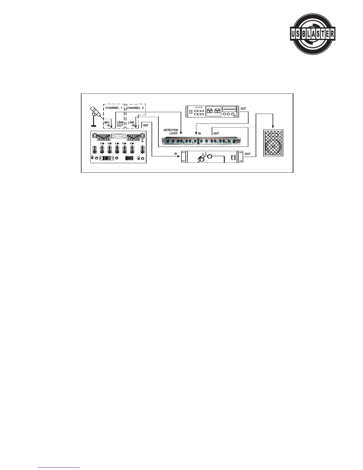
4. "VOICE-OVER" COMPRESSION ("DUCKING")
The compressor can be used to automatically reduce music to background level when an announcer is speaking through a
microphone. For this purpose, the compressor is used as an automatic fader and is controlled by the announcer's micro-
p
hone, which is connected to the DETECTOR LOOP, input via a preamplifier. The music output and the announcer's voice
are then mixed. This application is known as "voice-over" compression or "ducking" and is commonly used in discos, radio
s
tations, etc.
Voice-over" compressing using the COMPRESSOR
SPECIFICATIONS
INPUT
Type..........................................RF filtered, servo-balanced input
Connectors ............................................XLR and 1/4" TRS jacks
Impedance...............50K Ohms balanced, 25K Ohms unbalanced
Nominal Operating Level .................+4 dBu / -10 dBV switchable
Max. Input Level ....................+21 dBu balanced and unbalanced
CMRR ...........................................typically 40dB, >55dB@ 1kHz
DETECTOR INPUT
Type ...................DC de-coupled unbalanced input, 1/4" TRS jack
Impedance ............................................................> 20K Ohms
Max. Input Level ..........................................................+21 dBu
OUTPUT
Type .....................................Electronically buffered output stage
Connectors .................................................................XLR jacks
Impedance...................60 Ohms balanced, 30 Ohms unbalanced
Max. Output Lev
el
..................+21 dBu balanced and unbalanced
Bandwidth
........................................
20Hz to 20kHz, +0/ -0.5dB
Frequency R
esponse
.......................
0.35 Hz to 200kHz, +0/ -3dB
Noise...............................> -95dBu, unweighted, 22Hz to 22kHz
THD...............................0.04% typically @ +4dBu, 1kHz, Gain 1
IMD .......................................................0.01% typically, SMPTE
Crosstalk ............................................< -100 fB, 22Hz to 22kHz
Stereo Coupling ............................................True RMS detection
CMR@ 1 Khz.................................................................> 60 dB
EXPANDER/GATE SECTION
Type......................IRC (Interactive Ratio Control) Expander/Gate
Threshold..........................................variable (OFF to + 10 dBu)
A
ttack...............................................................< 1 ms/ 100 dB
Release.............................................................100 ms/ 100 dB
© US Blaster Europe BV
COMPRESSOR SECTION
Type........................IKA (Interactive Knee Adaption) Compressor
Threshold ..........................................variable (-40 to + 20 dBu)
Ratio...........................................................variable (1:1 to •:1)
Threshold Characteristics............................................Hard Knee
Manual Attack Time .....................variable (0.1 to 200 ms/20 dB)
Manual Release Time.....................variable (0.05 to 4 sec/20 dB)
Auto Attack Time................typ. 15 ms. @ 10 dB, 5 ms @ 20 dB,
..................................................3 ms @ 30 dB
Auto Release Time .............program dependent, typ. 125 dB/sec.
Output.................................................variable (-20 to + 20 dB)
DYNAMIC ENHANCER SECTION
Type .........................Dynamically controlled frequency correction
Process .........................................................variable (OFF to 6)
FUNCTION SWITCHES
IN/OUT........................................Bypass switches both channels
A
uto
.......................Program-dependent attack and release times
INDICATORS
12 segment GAIN REDUCTION meter
..............................
...............................1/2/4/6/9/12/15/18/21/24/27/30 dB
8 segment LEVEL meter ...
-30/-20/-10/=6/-3/0/+3/+6 dB
LED indicator for each function switch
INAUDIBLE LEDs ............................................................
................."+" / "-" indicates onset of the Expander/Gate
POWER SUPPLY
AC Voltage100-120/60HZ or 200-240/50HZ VAC selectable
Power consumption..............................................9 watts
Fuse .........................T200mA,50X20mm glass type 250V
P
ower Cord Connector .................Standard IEC receptacle
DIMENSION
......................................
44 X 482 X 165mm
WEIGHT...............................................................2.2 Kg
16
 Loading...