Prima di effettuare qualsiasi operazione su parti elettriche assicu-
rarsi che non vi sia tensione. Verificare che la tensione di alimenta-
zione corrisponda ai dati nominali dell’unità (tensione, numero di
fasi, frequenza) riportati sulla targhetta a bordo macchina. L’alla-
cciamento di potenza avviene tramite cavo bipolare e condutto-
re di protezione. La sezione del cavo deve essere adeguata alla
massima corrente assorbita e dovrà essere protetto da un
adeguato interruttore magnetotermico differenziale (IΔn=0,03 A).
La tensione di alimentazione non deve subire variazioni superiori a
± 5 %. Il funzionamento deve avvenire entro i valori sopra citati: in
caso contrario la garanzia viene a decadere immediatamente. I
collegamenti elettrici ai quadri di comando devono essere
effettuati da personale specializzato. Assicurarsi che la tensione e
la frequenza riportate sulla targhetta corrispondano a quelle della
linea elettrica di allacciamento. I collegamenti elettrici devono
essere realizzati a regola d’arte, in accordo con le informazioni
riportate sullo schema elettrico allegato all’unità e dovranno
tenere conto delle rispettive norme vigenti. Tutte le linee devono
essere protette all’origine a cura dell’installatore.
ATTENZIONE: NON ALIMENTARE EVENTUALI RESISTENZE CON VENTI-
LATORE SPENTO
Before starting any work on electrical parts, make sure that the
power is off. Check the power supply voltage is the same as the
nominal data for the unit (voltage, number of phases, frequen-
cy), shown on the nameplate on the machine. The power
connection must be formed using a 1p-n + earth cable. Pass the
electric cables into the machine and electrical panel via the
cable glands. Cables must have a cross section which is able to
handle the maximum power absorbed, and must be protected
by residual current operated circuit-breakers with integral
overcurrent protection (RCBOS) (IΔn=0,03A). The power supply
voltage must not fluctuate by more than ± 5%. The unit must
work within the values indicated above. If this is not the case, the
guarantee shall become null and void immediately. The electri-
cal connections to the control panel must be carried out by
qualified personnel. Make sure that the voltages and frequency
shown on the data plate correspond to those of the power
line.Carry out the connections in accordance with the local
technical standards. All the connections must be protected at
the source by the installer.
WARNING: DO NOT WORK THE ELECTRICAL RESISTANCE WHEN
THE FAN IS OFF
COLLEGAMENTI ELETTRICI
ELECTRICAL CONNECTIONS
Gli schemi elettrici sono disponibili sul sito www.utek-air.it
Electrical diagrams are available on the website www.utek-air.it
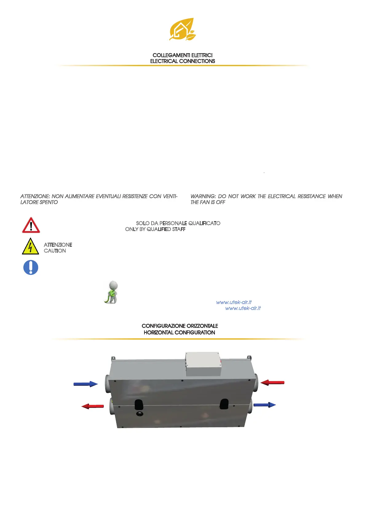
CONFIGURAZIONE ORIZZONTALE
HORIZONTAL CONFIGURATION
10
espulsione all’esterno
aria di rinnovo
immissione
estrazione dal locale
expulsion air
fresh air
supply air
exhaust air
Questa operazione deve essere svolta SOLO DA PERSONALE QUALIFICATO
This operation must be performed ONLY BY QUALIFIED STAFF
ATTENZIONE: prima di effettuare una qualsiasi procedura sull’unità assicurarsi che non vi sia tensione
CAUTION
: Before performing any procedure on the unit make sure that there is no voltage
DPI: dispositivi di protezione individuale
PPE: Personal Protective Equipment
 Loading...