ENGLISH
34
5
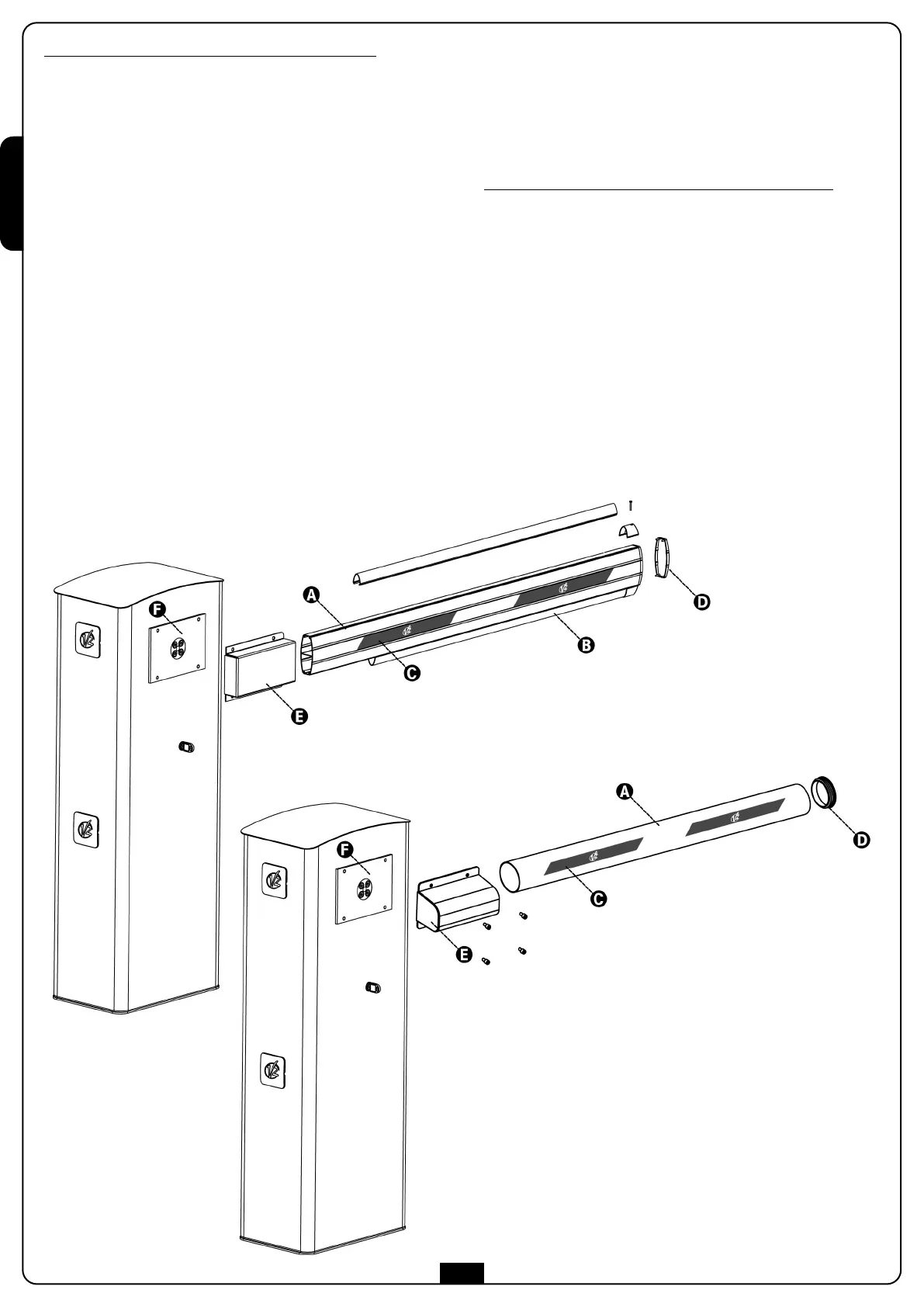
. Insert the cap D onto the boom
6. Mount bracket E on plate F, and screw in the 4 screws lightly
7. Insert the boom in bracket E until snug and screw in the
4 screws
For the round boom follow the following indications
1. Cut boom A to the desired length
2. Insert stopper D on the boom
3. Mount bracket E on plate F, and screw in the 4 screws lightly
4. Insert the boom in bracket E until snug and screw in the
4 screws
F
or the flat boom follow the following indications
1. Cut boom A to the desired length
NOTE: if the lights kit is required (code 163615), the modules
have to be installed before mounting the rubber edge
2. Mount the anti-shock rubber bumper strip B on the boom
(the rubber bumper strip must be 20 cm shorter than
the boom’s length)
NOTE: If the end support post is required (code 163605), the
rubber edge has to be shortened in order to avoid any contacts
with the support.
3. Apply the reflecting adhesive tape C (accessory code ACC076)
on the sides of the boom
4. Insert the two caps M onto the boom to seal the rubber edge.
Drill the aluminium profile with a 2,5mm drill bit and screw
the caps with the supplied screw
 Loading...