7
2. Installation
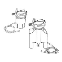
2.1 General description (fi g. 1)
a) Air inlet (1/4”) c) Lever lock e) Safety valve
b) Operation lever d) Silencer element
2.2 Preparation
Screw airline nipple of your quick connect coupling system into the air inlet (a).
Make sure that the drain valve of the canister is closed (type Drainman only).
3. Operation
3.1 How to use
Fig. 2 Connect bleeder to compressed air source (5.5 -12 bar /80-175 psi).
Fig. 3 1. Remove the master cylinder reservoir cap.
2. Press the top lever
3. Vacuum the old brake fl uid.
Fig. 4 Fill in new brake fl uid up to maximum level mark. To keep fl uid level
while bleeding, use the (optional) automatic refi ler kit.
Fig. 5 1. Make sure the wheel cylinder’s bleed screw is clean. If the vehicle
has a load sensitive valve, make sure it is open.
2. Slide the rubber fi tting over the nipple of the bleed screw (Note: on
some old GM models with recessed blee screws, use the appropri-
ate adapter socket.
Fig. 6 Press down the lever and open the bleed screw slightly until brake fl uid
is visible in the suction hose. Keep it open for 20-30 seconds (make
sure the master cylinder reservoir will not get empty).
Fig. 7 To stop bleeding, close the bleed screw and release the lever
Repeat step 5 to 7 on all bleed screws.
After bleeding, check brake pedal action to verify that air has completely
been removed. A brake check is the only way to make sure the brake
service is properly done.
4. Trouble shooting
4.1 Air bubbles in the vacuum hose even after bleeding for several seconds (fi g. 8)
This is normal. When using the vacuum principle, a small amount of ambient air
will pass the threads of the bleed screw into the vacuum line of the bleeder causing
bubbles or foam. This does not affect the bleeding of the brake circuit. A fi rm pedal
indicates complete and proper bleeding.
(If desired, a small amount of silicone grease or tefl on tape can be applied to
the threads of the bleed screw to eliminate these bubbles).
4.2 No fl uid drawn into the canister
1. Is bleed screw blocked by dirt? Remove, clean and replace bleed screw.
2. Is the car equipped with a load sensitive valve? Make sure it is open.
3. Is there fl uid in the system? Check fl uid level in the master cylinder reservoir
(if using automatic refi ller, make sure it is properly connected).
09-000-8010 innehåll.indd 7 2004-04-22, 15:36:37
Pr
ocess Cyan Process Magenta Process Yellow Process Black
 Loading...