www.vag-group.com
info@vag-group.com
We reserve the right to make technical
changes and use similar or higher-quality
materials. Drawings are non-binding. For
technical information we kindly refer to our
technical data sheet KAT-A 1613.
Inbetriebnahme
Putting into operation
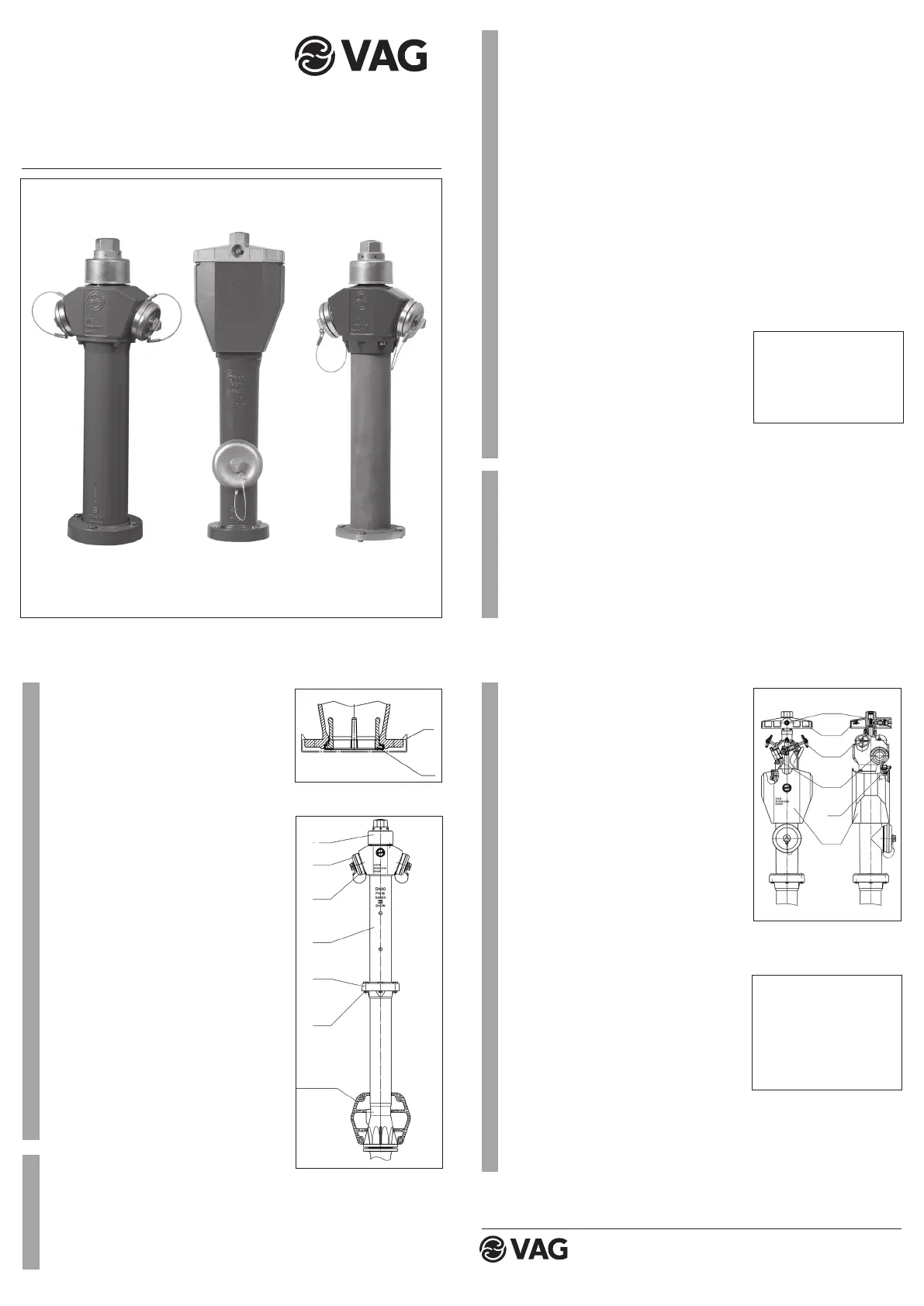
VAG NOVA 284 / NOVA NIRO
Überflurhydrant
VAG NOVA 284 / NOVA NIRO
Standpost Hydrant
2
1
• Open the upper shut-off valves (11).
• Using a T-key (to DIN 3223) or directly
by hand, open the main shut-off valve
by slowly and evenly turning the cover
(9) counter-clockwise until the clearly
noticeable limit stop is reached (11.5
turns/stroke).
• The locking bolt (14) is pressed to the
outside by the pressure generated and
thus locks the drop jacket in the lower
position.
• Warning!
The hydrant‘s main shut-off valve must
always be opened completely until the
clearly noticeable limit stop is reached!
3.2 Closing type AFUD
• Close the hydrant‘s main shut-off valve
by evenly turning the bonnet clockwise
until the clearly noticeable limit stop is
reached. (Do not use impermissible ope-
rating tools or extensions!).
• Close the outlet valves.
• Remove the coupling elements and ho-
ses from the fixed couplings.
• Observe draining. Manually turn back
the safety bolt (14), guide the drop ja-
cket (13) upward and lock it. This can
only be done when the main shut-off
valve is closed!
3
Figure 1
KAT-B2 1613
Edition 2 / 05-2010
Montage Form AUD und AFUD
• Remove the protective cap (8) before
placing the hydrant on the pipeline (Fig.
1).
• The sealing ring (7) is pressed in cap-
tively at the factory and is used as a
sealing for the pipeline flange. No additi-
onal seal required.
• After placing the hydrant on the pipeline
flange, tighten the screws and nuts
evenly and crosswise.
• Before backfilling the pipe trench, as-
semble a suitable drainage stone (Fig. 2)
for safe drainage of the hydrant.
• Additionally, the installation guidelines
set out in DVGW Code of Practice W
331, Section 5 must be observed!
• After backfilling the pipe trench, the up-
per pillar (4) of the hydrant can be subse-
quently adjusted via a special two-part
loose-flange connection (5). The hexago-
nal screws (6) are loosened at the rup-
ture nut connection and the upper pillar
(4) is turned in the desired position.
When tightening the hexagonal screws
(6), make sure the two screws at the flan-
ge joint are tightened first (maximum
tightening torque for DN 80 = 25 Nm and
for DN 100 = 38 Nm).
Putting into operation of type AUD (Fig. 2)
2.1 Öffnen Form AUD
• Unscrew the upper covers (2). Connect
the coupling element or hose with the
shut-off valve to the fixed couplings (3)
and open the shut-off valve.
• Insert the T-key DIN 3223 (type A or B)
into the cover (1) and turn the main shut-
off valve evenly counter-clockwise until
the clearly noticeable limit stop is
reached.
• DN 80 => 10 turns/stroke
• DN 100 => 11.5 turns/stroke
• Warning!
The hydrant‘s main shut-off valve must
always be opened completely until the
clearly noticeable limit stop is reached!
• The control of the extraction rate is only
permissible via a shut-off valve installed
downstream.
2.2 Closing type AUD
• Close the hydrant‘s main shut-off valve
by evenly turning the bonnet (1) clockwi-
se with a T-key DIN 3223 until the clearly
noticeable limit stop is reached.
• Remove the coupling elements or hoses
from the fixed couplings (3).
• Observe draining! Screw the covers (2)
on again tightly.
Putting into operation of type AFUD (Fig. 3)
3.1 Opening type AFUD
• Unfasten the lock of the drop jacket
using a T-key (according to DIN 3223).
The drop jacket (13) is now unlocked
and drops down.
• Connect the coupling elements and ho-
ses to the upper fixed couplings (12).
Attention!
Observe the closing sequence
acc. DVGW gudilines: First
close the hydrant’s main isolati-
on, not till then close the out-
lets.
2
3
Figure 3: Hydrant Type AFUD
Attention!
Observe the closing sequence
acc. DVGW gudilines: First
close the hydrant’s main isolati-
on, not till then close the out-
lets.
8
7
Figure 2: Hydrant Type AUD
1
2
3
4
5
6
Drainage
stone
10
9
11
12
14
15
Form / Type
AUD
Form / Type
AFUD
Form / Type
AUD
 Loading...