EasyManua.ls Logo

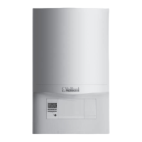
Vaillant ecoFIT pure 618 User Manual

Vaillant ecoFIT pure 618
60 pages
To Next Page IconTo Next Page
Page #1 background imageLoading...
Page #1 background image
en Installation and maintenance instructions
ecoFIT pure
612 - 630
0020230533_06 - 28.07.2020

Table of Contents

Question and Answer IconNeed help?

Do you have a question about the Vaillant ecoFIT pure 618 and is the answer not in the manual?

Vaillant ecoFIT pure 618 Specifications

General IconGeneral
Boiler TypeCombi
MountingWall-mounted
ERP RatingA
CH Output (kW)18
Efficiency (%)94
Dimensions (H x W x D)700 x 400 x 300 mm
Fuel TypeNatural Gas
Warranty2 years
Modulation Range1:6
Heating Flow Temperature Range30 - 80 °C
Maximum Working Pressure3 bar

Summary

1 Safety

1.3 General Safety Information

Provides essential safety information to prevent death, injury, or damage.

1.3.1 Gas

1.3.2 Flue Gas

1.3.3 Electricity

5.5 Safety Devices

7 Installation

7.4 Gas and Water Connections

Connecting gas and water supplies to the boiler.

7.8 Electrical Installation

7.8.4 Wiring the Product

Instructions for performing electrical wiring.

7.8.5 Establishing Power Supply

7.8.6 Connecting Controls

8 Operation

9 Start-up

9.1 Initial Start-up

Steps for performing the initial start-up using the checklist.

9.2 Heating Water Quality

Ensuring water quality and treatment for the heating system.

9.5 Insufficient Water Pressure

9.9 Gas Setting Checks

9.9.2 Gas Flow Rate

Procedure for checking the boiler's gas flow rate.

9.9.3 Gas Connection Pressure

Verifying the gas inlet working pressure.

9.9.4 CO2 Content Check

10 Adapting to Heating Installation

10.1 Burner Anti-cycling Time

Adjusting the burner anti-cycling time to prevent short cycling.

10.2 Setting Pump Output

Adjusting the speed-regulated pump output.

10.3 Setting Bypass Valve

10.4 Domestic Hot Water Temperature

11 Handing Over to End User

12 Inspection and Maintenance

13 Troubleshooting

13.5.1 Replacing the Burner

13.5.3 Replacing the Heat Exchanger

13.5.4 Replacing the Pump Head

13.5.5 Replacing the Expansion Vessel

13.5.6 Replacing the PCB

13.5.8 Replacing Expansion Relief Valve

13.5.9 Replacing Pressure Sensor

13.6 Checking Leak-tightness

14 Decommissioning the Product

Appendix D Fault Codes

Appendix G Commissioning Checklist

Appendix H Commissioning Flow Chart

Related product manuals