Do you have a question about the Vaillant TURBOmax Pro 28/2 E and is the answer not in the manual?
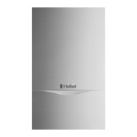
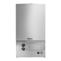
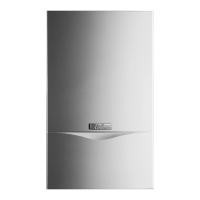
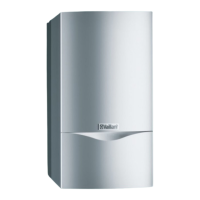
Boiler overview, hot water priority, sealed system design, 28kW output, flue options.
CE Mark compliance with directives and regulations.
Diagram and key for boiler connection points.
Lists standards for installation and safety compliance.
Guidelines for siting the boiler, considering space and regulations.
Requirements for gas supply pipework, size, and testing.
Details on top, rear, and extended flue system types and their uses.
Regulations for flue terminal positioning and clearances.
Recommendations for ventilation, especially in cupboards.
Requirements for power connection, earthing, and isolation.
Pipework insulation, draining taps, and system cleansing.
Procedures for filling the heating system with water.
Details on the safety valve's function and discharge pipe.
Information on the factory-fitted pressure gauge.
Sizing and installation of the CH expansion vessel.
Details on the pump's head and settings.
Information on the built-in system bypass.
Requirements for system venting, including automatic vents.
Optional accessory for domestic hot water expansion.
Required clearances around the boiler for installation.
Guide to using the template for accurate boiler mounting.
Steps for securely mounting the boiler bracket.
Instructions for fitting the air/flue duct.
Procedure for lifting and hanging the boiler onto the bracket.
Steps to safely remove the boiler's front casing.
Connecting the gas service cock and supply pipe.
Connecting water supply and outlet pipes.
Connecting heating circuit service valves.
Connecting the discharge pipe to the PRV.
Requirements for electrical work and compliance.
Wiring the boiler to the mains power supply.
Diagram showing connections on the electronic board.
Wiring diagrams for various thermostats.
Wiring details for external time switches.
How to connect an external frost thermostat.
Information on pump, anti-cycling, and pump spin controls.
Steps for reattaching the boiler casing and securing the panel.
Verifying electrical safety and polarity.
Inspecting, testing, and purging the gas installation.
Filling and purging the hot water system.
Step-by-step guide to filling the heating circuit.
Procedure for flushing the system before operation.
Checking and setting the gas pressure at the inlet.
Procedure for checking natural gas and LPG burner pressure.
Method for range-rating the central heating output.
Tables detailing burner pressures and gas rates.
General procedure for checking boiler operation.
Using diagnostic lights to check boiler status.
Checking DHW operation via indicator lights.
Checking central heating operation via indicator lights.
Adjusting pump speed and performing hot flush.
Instructions for user operation and maintenance advice.
Preliminary checks before servicing the boiler.
Verifying boiler functions after service.
Steps for cleaning key internal components.
Essential safety precautions before replacing parts.
Steps to prepare the boiler before part replacement.
Procedures for replacing burner and electrodes.
How to remove and replace the fan assembly.
Procedure for replacing the gas valve.
Replacing NTC sensors for temperature measurement.
Steps for removing and replacing the main heat exchanger.
Procedures for replacing the CH expansion vessel.
Steps for replacing the main control board.
Procedures for replacing pump and air pressure switch.
Procedures for replacing bypass and diverter valve.
Procedures for replacing pressure gauge and aqua sensor.
Procedures for replacing heat exchanger and PRV.
Final checks after part replacement.
Overview of diagnostic indicators and fault finding.
Step-by-step guide for diagnosing issues.
Essential checks before starting fault diagnosis.
Diagnosing faults via electrical, pump, fan, controls, flue, gas, burner, DHW.
Diagram showing the boiler's functional logic.
Diagram illustrating electrical connections.
| Output | 28 kW |
|---|---|
| DHW Output | 28 kW |
| Fuel Type | Gas |
| Fuel | Natural gas or LPG |
| Dimensions (H x W x D) | 700 x 400 x 300 mm |
| Weight | 34 kg |
| Mounting | Wall-mounted |
| Max. working pressure | 3 bar |
| Boiler Type | Combi |
| Electrical supply | 230 V |


