The VCX Control is a modular, integrated system designed for gluing control and quality assurance. It allows for the combination of Pattern Control Modules (PCM), Inspection Control Modules (ICM), Tracking Control Modules with Ejector (TCM-E), and Color Code Readers (CDS) with one or two VCX Controls to provide comprehensive functions for glue application, inspection, and quality assurance.
Technical Specifications:
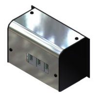
- Dimensions:
- Width: 19" [482.6mm]
- Height: 12" [304.8mm]
- Depth: 9.5" [241.3mm]
- Weight:
- Base unit weight: 33lb (15kg)
- Module weight: 4.5lb (2kg)
- Power:
- Voltage Range: 100-125VAC and 200-245VAC (Automatic Selection)
- Power Consumption: 800W max.
- Inputs and Outputs: I/O is dependent on the specific configuration of modules.
Usage Features:
The VCX Control operates through an OT-120 Terminal, which manages the system. The screen display on the OT-120 may vary slightly depending on the software revision installed.
Power Up Sequence:
- Press the Power On Button located on the bottom left of the OT-120.
- Plug in the VCX.
- Flip the power switch on the back of the VCX Power Supply Module to the "On" position.
- The Standby LED on the OT-120 Control will turn orange as the unit warms up, then green when it reaches full power.
Power Down Sequence:
- Press the Power Off Button on the bottom right of the OT-120 screen.
- Confirm exit when the dialog box appears.
- Wait until the Standby LED on the OT-120 Control turns orange as the unit powers down.
- Flip the power switch on the back of the VCX Power Supply Module to the "Off" position.
Module Configuration:
The Power Supply Module is always positioned on the left side of the VCX Control base. Additional modules are added from left to right, with Tracking Control Module(s) always placed in the rightmost slot(s).
Linking Two VCX Controls:
Two VCX Controls can be linked together. This involves:
- Disconnecting all power to both units and the OT Unit.
- Designating one control as "VCX-1" and setting its Control Selector Switch to "1".
- Designating the other control as "VCX-2" and setting its Control Selector Switch to "2".
- Replacing the covers on both units.
- Connecting the cables between "VCX-1", "VCX-2", and the OT-120 Unit.
- Reconnecting power and performing the power up sequence. Encoders can also be linked together.
CDS Color-Code Reader:
This versatile tool offers high-speed inspection functions, including mixed copy detection, missing color and color density, print registration, die-cut registration (lateral and longitudinal), and detection of skewed cartons and double feeds.
- Specifications:
- Colors: All
- Code types: Binary-type codes (EMS, Bobst, Pharma, Free-style)
- Machine speed: 600 m/min
- Limitations: Smallest code bar must be 0.5 mm wide, not suitable for dark-colored or holographic backgrounds.
- Suitability: Cartons with code pictures on the glue flap (using prefolder-mounted camera), black-and-white binary codes, color binary codes, and color bars.
White Value Calibration Procedure (for CDS Sensor):
This procedure is necessary during initial installation or after changing the halogen lamp to establish a baseline for white.
- Ensure the CDS sensor is clean.
- Adjust the pre-folder so cartons flow without interference or skewing, and the glue flap is at a 90-degree angle to the gluer belt surface. Use cartons with a pure white background.
- Follow online instructions to run four boxes past the sensor.
- The reading range should include approximately 5-6 mm of white clear space before the leading edge of the code picture.
Establishing a Baseline for the CDS Sensor:
For each sensor, a sample product must be run to establish a baseline code.
- Clean the CDS sensor, lamp, and photocell.
- With the sensor lamp off, jog a blank into the pre-folder and align the code picture between the two red dots.
- Ensure the box runs freely.
- Turn the sensor lamp ON and switch the MCU control to run mode.
- Press the icon for the CDS camera to view the glue flap. The picture should be "clean" with pixels between bars.
- After cartons have run, a message will confirm success and recommend sampling for the code.
- Ensure the folding section is empty and the ejector is on.
- Using one blank, sample the code reader.
It is crucial to sample with a good quality carton, as all subsequent cartons will be compared to this master. The sampled carton will be ejected.
Encoder Installation:
An encoder is required to determine the parent machine's speed. For optimal results, 100 pulses per inch (25.4 mm) of product travel should be supplied.
- Wheel-Driven Encoder: A VDD-1000 encoder with a 10-inch measuring wheel is recommended. Mount its bracket to the machine frame, ensure the wheel rides securely without slipping, and set ratio compensation to 100 pulses in the level-4 menu.
- Gear-Driven Encoder: Install the driver gear on the line shaft and tighten set-screws. Position the encoder square with the driver gear and tighten the belt against the driver gear. At least 7-9 teeth should engage. An adjustable bracket may be needed.
Maintenance Features:
Removing/Adding Modules:
- Removal: Turn off all power and disconnect the power cord. Use a hex wrench to unhook the four latches on the cover. Carefully lift the cover off. Disconnect all cables/plugs from the module's back. Loosen screws securing the module to the base rails and slide it out. Replace the cover and reconnect power.
- Addition: Turn off all power and disconnect the power cord. Remove the cover. Slide the module into the VCX Control base, ensuring it slides easily and the locator pin matches the mating connector. Secure the module with screws. Connect appropriate cables/plugs. Reconnect the power cord and follow the power-up sequence.
Disk Utilities for Unit Data Recovery:
- Open a terminal program (e.g., HyperTerminal) on a PC.
- Select direct communication to a serial port (e.g., COM1) and configure settings (19200 baud, no parity, 8 data bits, 1 stop bit, no handshaking, TTY emulation).
- Type 'help' and 'dir' to view available commands and file structure.
- Run 'bak' to create a current image of setup data.
- Run 'dir' again to verify 'Backup.ibs' is created. Identify an unused job number (e.g., not 'Job0001.ibs' through 'Job0099.ibs').
- On the MCP-4, perform a job storage for the selected number and verify with 'dir'.
- To copy files to the PC, use 'ulf ' and select the 'Transfer send' option with Y-Modem and a storage location (e.g., C:\customer_data<partnum>+).
VTerminal for Software Updates:
Requires a PC/Laptop with Windows 98/95, NT, 2000, or XP, VTerminal software, and a Null Modem Cable.
- Switch off the unit and connect the PC to the diagnostic port with the Null-Modem cable.
- Start VTerminal, select 'Tools' and 'Software Update'.
- The program will show connection status. Switch on the unit.
- Confirm the update by pressing 'Y' within 5 seconds.
- Select the new program software file (Motorola-S Record format, '.s28' extension) and click 'Open' to start the download and programming. The download may take up to 7 minutes. Canceling or corruption requires restarting the procedure. Successful programming will display a confirmation message.