Do you have a question about the Valcom VIP-148L and is the answer not in the manual?
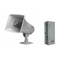
The Valcom VIP-148L IP Talkback Horn is a network-enabled device designed to provide two-way, hands-free voice communication to a single location over an IP-based network. This allows for the extension of a page zone to any point within the network infrastructure. The horn's audio level can be adjusted electronically via software, offering flexibility in sound output. For call initiation, a call switch input connection is provided, and a line-level auxiliary input is available for connecting a local audio source, such as background music. The VIP-148L receives power through a Power over Ethernet (PoE) switch that complies with the 802.3af specification, simplifying installation by eliminating the need for a separate power supply.
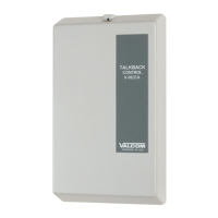
The VIP-148L integrates seamlessly into various communication environments. It can operate with PBX systems using an FXO port in conjunction with a VIP-811, or with a standard POTS telephone set also utilizing a VIP-811. For SIP-based telephone systems, it supports direct integration, and for FXS port applications, it can be used with a VIP-821. This versatility ensures compatibility with a wide range of existing telephone infrastructures. The device is equipped with an RJ-45 connector for network connection, facilitating straightforward integration into IP networks. It also features an LED Status Indicator and Network activity LEDs, providing visual feedback on its operational status and network connectivity.
One of the key usage features of the VIP-148L is its ability to broadcast background music through its auxiliary input. This input accepts line-level audio, allowing for the distribution of music or other audio content. During announcements or active calls, the auxiliary input is automatically muted and remains muted until the communication is terminated, ensuring that voice pages are clear and uninterrupted. The device is designed for both indoor and outdoor installation, making it suitable for a variety of environments, from office buildings to industrial settings. Its robust construction ensures reliable performance in different environmental conditions.
The VIP-148L Network Interface is designed for either wall or table mounting and must be located within 100 meters of the network switch to ensure optimal performance. For wall mounting, wood screws are provided to secure the unit. The horn itself offers flexible mounting options. It can be mounted to a beam using the provided "C" clamp, which allows for maximum positioning adjustments. The bolt for the "C" clamp is inserted through a hole in the bottom of the base. Alternatively, the horn can be connected to an electrical backbox. This is achieved by channeling wire through the ball of the base and making the necessary electrical connections. The base is pre-punched for a double-gang square box, but additional knockout holes can be removed to accommodate single-gang or octagon boxes.
To achieve the desired position, the horn can be rotated or moved up and down by loosening the position adjustment knob, located at the bottom of the unit, approximately one turn. Once the desired position is set, the knob should be retightened. For optimal sound distribution, it is recommended to mount the horns 15 to 20 feet above the floor. The speaker can be attached to the base either before or after the base is mounted. This involves loosening the position adjustment knob, inserting the ball of the base into the speaker's socket, and then tightening the knob. The base can also be mounted directly to a wall using two pre-drilled holes, with additional knockout holes available if more mounting points are needed.
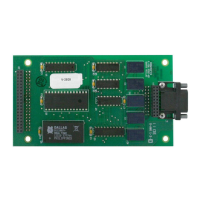
Connecting the VIP-148L to the network involves using a standard Ethernet patch cable to link the VIP-148L Network Interface to an Ethernet switch. For signal connections between the Network Interface and the horn, an RJ-45 patch cable conforming to EIA/TIA 568A or 568B Standard should be used. This cable connects to the horn connector of the Network Interface and then to the VM-186 RJ-45 connector. Specifically, the Brown and White/Brown pair of wires should be connected to the horn. An optional normally-open call button can be connected to the Blue and White/Blue pair of the horn RJ-45 connector, with the VM-186 RJ-45 connector providing easy access for these connections.
The VIP-148L Network Interface features two status indication lights on its side panel. The "LINK" light illuminates to indicate a 100 Mbit Ethernet connection; if it is not lit, it signifies a 10 Mbit connection. The "ACT" light flashes to indicate network activity, providing a quick visual check of the device's operational status.
For initial setup and programming, the VIP-148L requires configuration using a computer. The PC used for programming must be connected to the same subnet as the VIP-148L. The setup process is performed using the IP Solutions Setup Tool, which can be downloaded from the Valcom website. This tool allows users to customize various parameters specific to their application, ensuring the device functions optimally within their network environment.
In terms of maintenance, Valcom emphasizes that its equipment is not field repairable. Should any issues arise, technical assistance is available from the factory. Users can contact Valcom's technical support line or visit their website for troubleshooting guidance. If repairs are necessary, the unit should be returned to Valcom's Repair & Return Department. When returning a unit, it is essential to attach a tag clearly stating the company name, address, phone number, contact person, and a detailed description of the problem. This ensures efficient processing and repair.
Valcom provides a limited warranty for its products, covering defects in materials and workmanship under normal use and service for one year from the date of shipment. This warranty is limited to replacement, repair, or refund of any defective device, provided that the claim is validated by Valcom, the defect is not a result of damage, misuse, or negligence after shipment, the product has not been altered or repaired by unauthorized personnel, and factory-sealed units remain unopened. Freight charges for returning products to Valcom must be prepaid. Units that are out of warranty are subject to a service charge, which covers minor repairs, with major repairs incurring additional charges for parts and labor. The warranty explicitly excludes anticipated profits, consequential damages, loss of time, or other losses incurred by the buyer. The maximum liability under the warranty is limited to the purchase price of the specific product. The product is provided "as-is" without any other warranties, including merchantability, fitness for a particular purpose, or non-infringement. Damage incurred during shipment is also excluded from the warranty, and such claims should be filed with the carrier involved.
| Type | Intercom System |
|---|---|
| Model | VIP-148L |
| IP Address | Static or DHCP |
| Audio Output | Built-in speaker |
| Mounting | Wall mount |
| Color | White |
| Description | VoIP Intercom |
| Power Supply | PoE (802.3af) |
| Protocols | SIP |
| Material | Plastic |
| Operating Temperature | -20°C to +55°C |