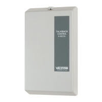
EasyManua.ls Logo

Valcom V-2924A User Manual

Valcom V-2924A
16 pages
To Next Page IconTo Next Page
Page #1 background imageLoading...
Page #1 background image
Issue 8
1 947211
V-2924A
TALKBACK INTERCOM SYSTEM
EXPANDABLE 24/48/72/96 ZONE
CONTENTS
INTRODUCTION 1, 2
SPECIFICATIONS 2, 3
INSTALLATION 3, 4
Precautionary Information 3, 4
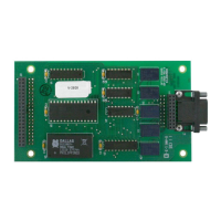
V-2924A Control/Connector Locations 5
Punchdown Block Connections 6
Attendant Port Connection 7
Background Music Connection 7
Door Speaker/Call Switch Connection 7
Inhibit Option 8
External Tone Source (ex.V-9927A) 8
SMDR Printer Port Cable 8
Override Page Port 9
Global All Call Page 9
Global Priority Page 9
Zone Page Option 10
Clock Sync 10
Dip Switch Options 11
OPERATION 12, 13, 14
Remote Station Access (Call Button) 13
Attendant Station Dialing Plan 13, 14
TROUBLESHOOTING CHART 14
LIMITED WARRANTY 14
TECHNICAL ASSISTANCE 15
GLOSSARY OF TERMS 16
The V-2924A Talkback Intercom System provides 24 stations with one-way, two-way, group call and all call pages.
Each station can be programmed for one-way or two-way communication. The stations may be grouped into one-
way page groups. The system also provides the ability for a remote speaker location equipped with a call button to
call the attendant location. The attendant receives calling speaker identification when using a Caller ID equipped
telephone or a Caller ID display.
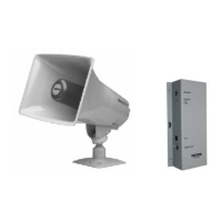
The V-2924A is compatible with standard 45 Ohm speakers and one-way amplified speakers and can be accessed
via a single line phone, E-Key line port or PABX loop start trunk port. An RS-232 port on the control unit provides
a connection for a serial printer for printout of system activity.
The V-2924A provides a background music input and is designed to automatically mute music during a page. The
basic system also provides four (4) contact closures associated with the last 4 zones to allow for door strike plate
activation. Multiple V-2924A control units can be interconnected to allow global all call and global priority pages
for up to six (6) V-2924A control units.

Other manuals for Valcom V-2924A

Questions and Answers:

Valcom V-2924A Specifications

General IconGeneral
BrandValcom
ModelV-2924A
CategoryIntercom System
LanguageEnglish

Summary

Introduction

Specifications

Attendant Port

Details connection and specifications for the attendant telephone port, including access types and impedance.

Ring Supply

Specifies the voltage and frequency for the ring signal, including different ring patterns.

Override Page Port

Describes the connection and function of the override page port for system access.

Installation

Precautionary Information

Safety precautions to follow before installation of the unit.

V-2924A Control/Connector Locations

Identifies physical locations of controls and connectors on the V-2924A unit.

Punchdown Block Connections

Details wiring connections for speaker outputs, switch inputs, and system inputs.

Attendant Port Connection

Illustrates how to connect the attendant telephone or system line.

Background Music Connection

Shows the wiring diagram for connecting a background music source.

Door Speaker/Call Switch Connection

Diagrams for connecting door speakers and call switch inputs.

Inhibit Option

Explains the wiring for the inhibit feature using a dedicated telephone.

External Tone Source (ex.V-9927A)

Details connections for an external tone source like the V-9927A.

SMDR Printer Port Cable

Shows the cable connection for an SMDR printer.

Override Page Port

Illustrates the connection for the override page port.

Global All Call Page

Describes how to set up global all call paging across multiple units.

Global Priority Page

Explains the setup for global priority paging across multiple units.

Zone Page Option

Details the configuration for one-way zone paging.

Clock Sync

Shows how to connect a master clock for system time synchronization.

Dip Switch Options

Explains the function of various dip switches for system configuration.

Operation

Originate a Handsfree Page

Steps to initiate a handsfree page from the attendant station.

Originate a Group Page

Steps to initiate a group page using dial access codes.

Originate a "Serial" Group Page

Procedure for originating a serial group page using specific codes.

Originate an All Call Page

Steps to originate an all call page to all stations.

One-Way Page with Meet Me/Follow Me

How to locate an individual using one-way paging.

Inhibit

Functionality of the inhibit feature for single line telephones.

Override Page Port

How the override page port affects system activities.

Queue Operation

Explanation of how calls are placed in and managed by the queue.

Placing a Call from a Speaker

Procedure for initiating a call from a talkback speaker to the attendant.

Placing a Call from a Door Box

Procedure for initiating a call from a door box to the attendant.

Remote Station Access - Call Button

How to initiate calls to the attendant using call button presses.

Attendant Station Dialing Plan

Outlines dial codes for accessing stations and groups from the attendant console.

Troubleshooting Chart

Limited Warranty

Technical Assistance

Glossary of Terms

Related product manuals