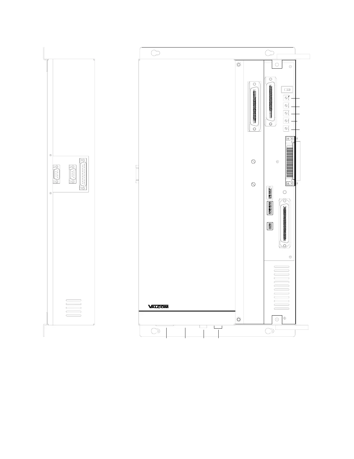
5
Side View
Top View
R79
R80
R82
R115
R81
P3
P7
P8
R16
R11
SW2
SW3
SW1
P10
P6
P10
AC
Power
Fuse115/230
Switch
Battery Backup
Connector
Switches:
SW1
SW2, SW3
SW4
- BGM Group Select Dip Switch (See Table 1)
- Option Dip Switch (See Table 1)
- Battery Feed Switch (Priority Port)
Volume Controls:
R11
R16
R79
R80
R81
R82
R115
- Handsfree Speaker to Phone Level
- Handsfree Phone to Speaker Level
- Background Music Level
- External Tone Source Level
- All Call Adjust Volume/Attendant Level
- Override Port Page Level
- Internal Tone Source Level
P3
P6
P7
P8
P10
- 45 ohm Speakers (See Figure 2)
- Call-In Switch Inputs (See Figure 2)
- System Connections (See Figure 2)
- Expansion Unit Connector
- RS232 Serial Port for SMDR (DB9 Connector)
FIGURE 1 - 2924A CONTROL AND CONNECTOR LOCATIONS
SW4
Connectors:
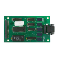
V-2924A