9
P7 Connecting Block
42
17
44
19
P7 Connecting Block
44
19
P7 Connecting Block
44
19
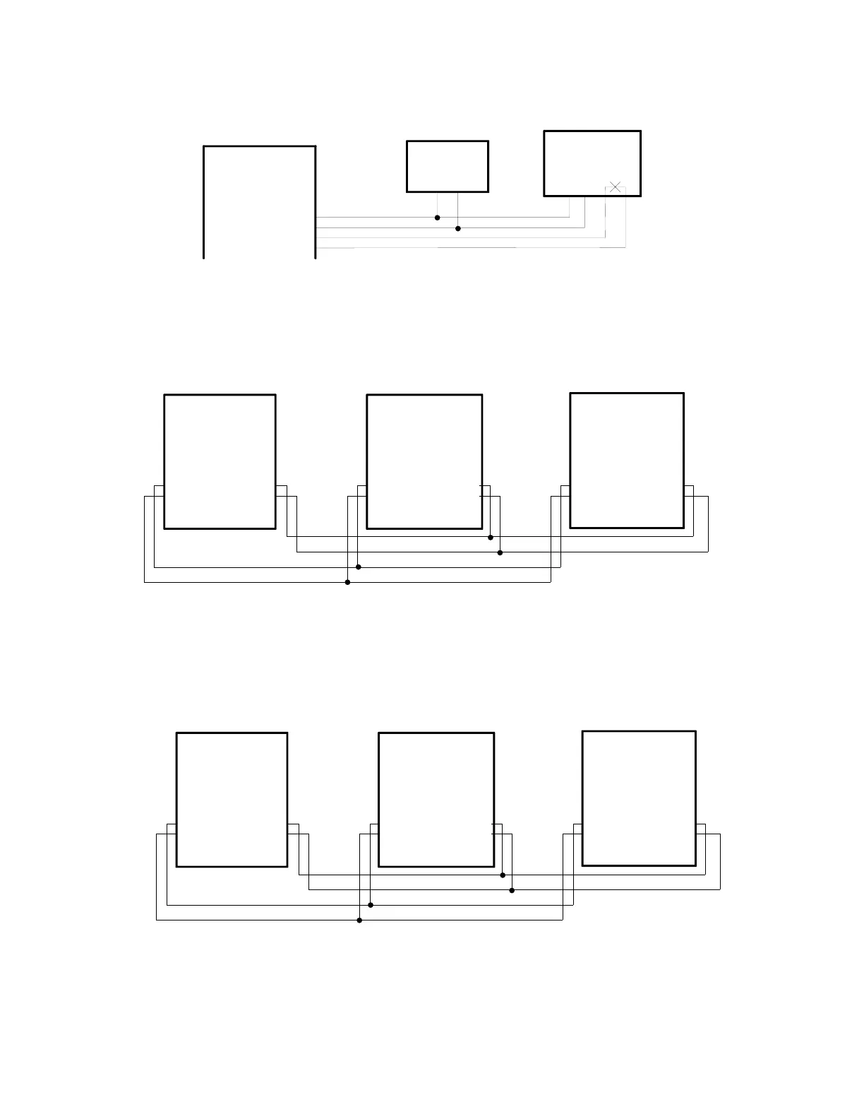
GLOBAL PRIORITY PAGE (FROM OVERRIDE PAGE PORT)
42
17
42
17
V-2924A #1 V-2924A #2
V-2924A #3
NOTE: Global all call page requires dip switches (SW3-4, SW3-5) to be set
on each V-2924A control unit to enable feature.
Y/O
O/Y
Y/BR
BR/Y
Y/O
O/Y
Y/BR
BR/Y
Y/O
O/Y
Y/BR
BR/Y
P7 Connecting Block
43
18
44
19
P7 Connecting Block
43
18
44
19
P7 Connecting Block
43
18
44
19
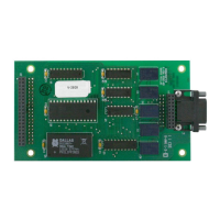
NOTE: Global all call page requires dip switches (SW3-4, SW3-5) to be set
on each V-2924A control unit to enable feature.
GLOBAL ALL CALL PAGE (FROM ATTENDANT DIAL UP)
V-2924A #1 V-2924A #2
V-2924A #3
Y/G
G/Y
Y/BR
BR/Y
Y/G
G/Y
Y/BR
BR/Y
Y/G
G/Y
Y/BR
BR/Y
P7 Connecting Block
Tel System
Page Port
(SW4 OFF)
Telephone
(SW4 ON)
OR
35
10
36
11
OVERRIDE PAGE PORT
SW4 on the control board
must be set accordingly
R/S
S/R
BK/BL
BL/BK
TR