Do you have a question about the Valleylab Force EZ - C Series and is the answer not in the manual?
General safety guidelines and best practices for handling electrosurgical equipment.
Crucial safety information regarding hazards and precautions during operation and servicing.
Specific warnings about fire and explosion risks associated with electrosurgical procedures.
Detailed information on preventing electrical shock during generator use and maintenance.
Precautions and guidelines for safe and proper servicing of the generator.
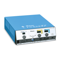
Overview of the electrosurgical generator's purpose, features, and capabilities.
Identification of the main parts and internal components of the generator unit.
Explanation of the generator's automatic resistance sensing and output adjustment feature.
Information on the system that monitors patient return electrode contact quality.
Detailed description of controls, displays, and indicators on the generator's front panel.
Explanation of the controls and receptacles located on the generator's rear panel.
Information about the serial and RF activation ports located on the option panel.
Overview of the generator's general performance, dimensions, and operating parameters.
Information on the standards and IEC classifications the generator complies with.
Available power settings in watts for various modes.
Graphs illustrating output power versus load resistance for various modes.
General explanation of how the electrosurgical generator functions.
How the REM system monitors contact quality and prevents burns.
Description of the Control board's functions and interfaces.
Overview of the main and feedback microcontrollers and their roles.
Description of the main board containing the high voltage power supply and RF output stage.
Circuit that interrupts power to reduce sparking.
Step-by-step instructions for setting up the electrosurgical generator.
How to properly connect accessories for bipolar surgery.
How to properly connect accessories for monopolar surgery.
Procedures for performing regular safety checks on the generator.
Procedures for verifying the generator's functionality through self-tests.
Step-by-step guide for calibrating the generator to ensure accuracy.
Initial steps to inspect the generator for obvious physical problems.
Table of common malfunctions, their causes, and recommended actions.
Guide to interpreting system alarms and taking corrective actions.
Procedures for troubleshooting and correcting malfunctions related to integrated circuits.
Steps to troubleshoot and resolve problems with the battery-backed RAM.
Procedure for replacing the battery for the battery-backed RAM.
Step-by-step guide for replacing the Control board.
Procedures for removing and installing the Display board.
Procedure for replacing the entire Footswitch board assembly.
Steps for removing and installing the complete front panel assembly.
Instructions for replacing various fuses in the generator.
Procedures for removing and installing the Power Supply/RF board and heat sinks.
Defines the manufacturer's responsibilities regarding the generator's safety and performance.
Steps and information required for returning the generator for service.
Information on how to find worldwide Valleylab service centers.
Information needed when ordering replacement parts for the system.
Exploded view of the generator assembly and its numbered parts.
A comprehensive list of parts for the generator assembly with part numbers.
List of components and part numbers for the Power Supply/RF board.