Valor Fitness
______________________________________________________________________________
____________________________________________________________________________________________________________________________________________________________
www.ValorFitness.com
3450 Morris Street North, St. Petersburg, Florida 33704
Phone: (727) 895-9525 Fax: (727) 895-9502 E-mail: info@ValorFitness.com
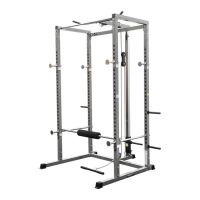
BD-17 Assembly Instructions
Note: The following step by step is a guide to walk you through what may be the best way to proceed.
The Assembly Instructions will guide you through the critical parts to assemble in sequence but may
also leave out some items that can be assembled by visual. Some parts may be already attached to
main frame parts. If you have any questions during the process, please call 727-895-9525 or e-mail
info@ValorFitness.com
Step #1: Main Frame (the goal here is to establish a solid structure to work from)
1. Attach part #14 Cross Bar to both uprights #11 & #12 using part #1 M10 x 20 Bolt and
Washers.
2. Slide part #15 Height Adjusting Sleeve over the top of each main frame. Lower the sleeve
near the bottom of the upright while you finish the rest of the parts. If part #8 Popper Pin is
not already inserted into the back of the Adj. Sleeve then go ahead and do so at this time. Do
this for both uprights.
3. Slide part #17 Short Adj. Sleeve down the main frame just like you did with the Height Adj.
Sleeve. Secure into desired height by the Popper Pin #8. Do this for both uprights.
4. Place part #9 Tube Bushing on top of main frame. This is just a cap for the top of the frame.
5. Slide part #13 Height Adj. Bar inside the main frame. When the bar comes in contact with the
Popper Pins you will need to pull the spring loaded pin out to allow the bar to travel further
inside the main frame.
6. There should be two rubber strips. These are protective strips that will be fastened to part #15.
Remove the tape from the back and apply to the sleeve.
7. Locate parts #18 and #19. These are safety catches that will be used during the Weight Bars
plate changing process. There is a correct left and right for these two parts. Refer to the line
art drawing to see which one goes on left or right. It does make a difference. Follow the
diagram.