Do you have a question about the VALPES VRX 25 and is the answer not in the manual?
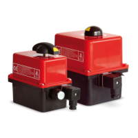
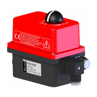
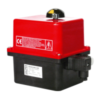
Brief overview of the product's purpose and application scope.
Guidelines for safe handling, packaging, and storage conditions.
Procedures for maintenance, troubleshooting, and service contact information.
Details of the product warranty terms, conditions, and coverage.
Policy and procedure for returning merchandise for compliance checks.
Critical safety guidelines for installation, operation, and product handling.
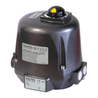
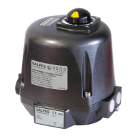
Description of the modular position indicator for VRX actuators.
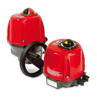
Description of the position indicator for VSX actuators.
Technical drawings and measurements for VRX actuator mounting and interface.
Technical drawings and measurements for VSX actuator mounting and interface.
Step-by-step instructions for manual operation of VRX actuators.
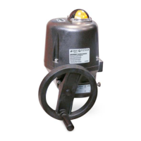
Instructions for using the manual override function on VSX actuators.
Procedures for installing VRX actuators and removing the cover.
Procedures for installing VSX actuators and removing the cover.
General guidelines for connecting actuator wiring.
Overview of available electrical circuit diagrams.
Detailed instructions for connecting power and control signals.
Instructions for wiring the auxiliary feedback signal.
Procedures for adjusting the actuator's end limit switches.
Schematics illustrating the internal electronic boards.
Identification and labeling of components on the electronic cards.
Common issues, symptoms, and troubleshooting for electronic card failures.
Technical diagrams showing actuator electrical connections.
Various wiring options for customer integration.
Identification of components within the three-phase diagram.
Important considerations for motor power supply and operation.
Overview of FAILSAFE model features and specifications.
Schematic illustrating the electrical setup for FAILSAFE models.
Explanation of the failsafe system's functionality and operation.
Detailed schematic of the FAILSAFE electronic control card.
Identification of components on the FAILSAFE electronic card.
Meaning and interpretation of status LEDs on the card.
Comprehensive wiring diagram for the FAILSAFE system.
Description of available safety mode configurations.
Information regarding the electronic card used in POSI models.
Details on connecting POSI model wiring.
Overview of electrical wiring schematics for POSI models.
Step-by-step guide for configuring POSI parameters.
Explanation of different input signal types for POSI models.
Detailed schematic of the P5 positioning card.
Identification of components on the P5 positioning card.
Information on actuators configured at the factory.
Detailed wiring instructions for POSI control and feedback signals.
Technical schematic showing POSI electrical connections.
Key information and requirements for POSI wiring.
Guide to setting shunts for POSI parameter configuration.
Procedure to select the operating direction of the valve.
Method for selecting the type of input control signal.
Steps to activate and use the learning mode for valve positions.
Description of the standard operational mode for POSI.
Description of GF3 actuators with three-position capability.
Details on the specific contacts used in GF3 models.
Diagram illustrating terminal assignments for GF3 actuators.
Detailed electrical schematic for GF3 actuators.
Identification of components within the GF3 schematic.
Illustrated breakdown of actuator assembly and parts.
List of all actuator parts with their names and references.
Specifications on operating conditions, physical dimensions, and mechanics.
Electrical characteristics, power, and performance data for VRX models.
Specifications on operating conditions, physical dimensions, and mechanics.
Electrical characteristics, power, and performance data for VSX models.
Details on ATEX classification, hazardous area usage, and conditions.
Statements confirming adherence to EMC, Low-voltage, and Machinery directives.
| Brand | VALPES |
|---|---|
| Model | VRX 25 |
| Category | Controller |
| Language | English |