4
20. ENGINE
Issue No.
1
02.12.2013
Model
A53/63/73
Code
210
Page
3
Engine Design
When the camshaft is viewed from the front of
the engine, the camshaft rotates in the following
direction: ................................................... Clockwise
The front of the engine is opposite the fywheel end.
The left side and the right side of the engine are
viewed from the flywheel end. The No. 1 cylinder is
the front cylinder.
Fuel Injection Lines
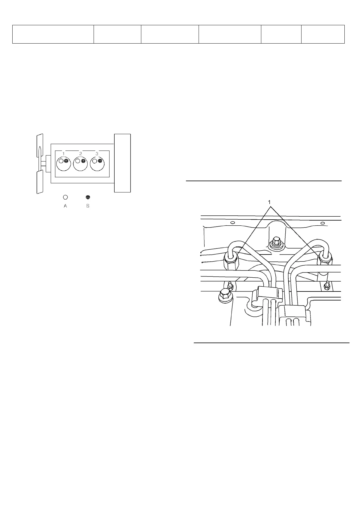
Illustration 1
Cylinder and valve location
(A) Inlet valve
(B) Exhaust valve
Bore ......................................... 105 mm (4.133 inch)
Stroke ...................................... 127 mm (5.000 inch)
Displacement ...................................... 3.3 L (201 in3)
Cylinder arrangement ..................................... In-line
Type of combustion ............................ Direct injection
Compression ratio
Naturally aspirated engines ...................... 19.3:1
Turbocharged engines .............................. 18.2:1
Number of cylinders ................................................ 3
Valves per cylinder .................................................. 2
Inlet valve ......................... 0.20 mm (0.008 inch)
Exhaust valve ................... 0.45 mm (0.018 inch)
Firing order ................................................. 1, 2, 3
When the crankshaft is viewed from the front of
the engine, the crankshaft rotates in the following
direction: ................................................... Clockwise
Illustration 2
Typical example
(1) Tighten the union nuts for the fuel injector nozzles
to the following torque. ............. 27 N·m (20 lb ft)
Tighten the union nuts for the fuel injection pump (not
shown) to the following torque. ....... 27 N·m (20 lb ft)

 Loading...