Do you have a question about the Van's Aircraft RV-7 and is the answer not in the manual?
Introduction to the flight manual and its purpose for safe operation.
Outlines the aircraft's experimental classification and operating categories.
Defines the meaning of warning, caution, and note indicators used throughout the manual.
Provides definitions for aviation terms and abbreviations used in the manual.
Details conversion factors between SI and US customary units for various dimensions.
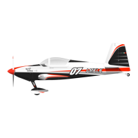
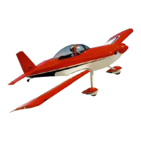
Presents a three-view schematic diagram of the aircraft.
Lists detailed physical and performance specifications of the aircraft airframe.
Introduces the scope of Section 2, covering operating limitations and placards.
Details critical airspeeds, including never-exceed, maneuvering, and stall speeds.
Explains the color-coded arcs and lines on the airspeed indicator.
Provides specifications for the engine, propeller, and their operating parameters.
Describes the markings and ranges for engine instrument indicators.
Covers markings for instruments not related to the powerplant.
Explains the function and display of warning, caution, and status lights.
Specifies the empty, maximum gross, and aerobatic gross weights of the aircraft.
Defines the datum and lists the forward and aft CG limits for flight.
Lists approved aerobatic maneuvers and their suggested entry speeds.
Details the G-load limits for various aircraft weights during maneuvers.
Specifies the aircraft's ceiling and provides a caution regarding oxygen use.
States the minimum crew requirement and seat operation.
Defines the approved types of flight operations, VFR and conditions.
Lists fuel tank capacity, total fuel, usable/unusable fuel, and grades.
Outlines requirements for the electrical system, including alternator functionality.
Specifies the maximum recommended crosswind component for takeoff and landing.
Indicates the availability of an extra seat for a passenger.
Lists required placards and markings for certification of the experimental aircraft.
Explains the purpose of the section for coping with emergencies.
Covers emergency procedures related to electrical system failures and configurations.
Details procedures for engine failures, rough running, and low oil/fuel pressure.
Outlines procedures for flap system faults, runaway trim, and autopilot issues.
Provides procedures for engine/fuel fires and electrical fires in flight.
Includes procedures for unintentional spins and suspected carbon monoxide.
Introduces normal operation procedures, checklists, and sequencing.
Contains detailed step-by-step procedures for all phases of normal flight operations.
Lists key airspeeds for normal flight phases like rotation, takeoff, and approach.
Describes the pre-flight checks for the cabin interior and exterior walk-around.
Details the pre-start checklist items and actions required before engine ignition.
Outlines checks and procedures after engine start and before taxi.
Provides guidance on taxiing procedures, including brake checks and throttle settings.
Lists the comprehensive checklist for pre-takeoff checks and procedures.
Details procedures for after takeoff, including gear retraction and climb power settings.
Covers procedures and checks for the cruise phase of flight.
Outlines procedures for approach, landing, and briefing.
Describes the procedure for executing a go-around from approach.
Lists procedures and checks to be performed after landing.
Details the steps for engine shutdown, securing the aircraft, and post-flight checks.
Provides instructions and precautions for refueling the aircraft.
Offers important operational advice and handling tips for the aircraft.
Explains procedures for ground handling with and without a towbar.
Introduces the section on aircraft performance, tables, and diagrams.
Contains charts and tables detailing aircraft performance characteristics.
Details the calibration of airspeed readings.
Lists stalling speeds under various configurations and power settings.
Provides takeoff run and distance data for various conditions and altitudes.
Offers landing run and distance data under different conditions and altitudes.
Presents a table correlating engine settings with cruise and endurance.
Explains the relationship between pressure and density altitude with a chart.
Details the endurance capabilities of the aircraft.
Emphasizes the importance of operating within the permissible mass and balance envelope.
Defines the reference datum plane for CG calculations.
Provides a template for recording aircraft mass and balance data over time.
Covers calculations and scenarios for flight mass and CG determination.
Lists key lever arms relative to the datum for CG calculations.
Details the calculation and values for the aircraft's basic empty weight and CG.
A form for calculating weight and balance for specific loading scenarios.
Presents calculated loading scenarios based on typical weights.
Graphical representation of the aircraft's CG limits for different flight conditions.
Lists all installed equipment approved for the aircraft.
Describes the experimental nature of the aircraft and builder's role.
Details the aircraft's aluminum semi-monocoque construction and wing design.
Explains the dual control system, elevator, aileron, and rudder operation.
Details the mechanical linkages for elevator, aileron, and rudder control.
Describes the electric flap actuation mechanism and its control.
Explains the pitch and aileron trim systems and their operation.
Overview of the glass cockpit instrument panel layout and functionality.
General description of the modern experimental glass cockpit.
Details the Dynon SkyView system, its components, and resources.
Describes the Garmin GNC 225 COM/NAV radio, its features, and frequencies.
Explains the PMA8000BT audio panel's functions for managing communications and audio sources.
Details the Garmin AERA 795 GPS navigator and its aviation features.
Describes the PLX wideband AFR gauge for engine monitoring.
Covers standby instruments including Dynon D6 EFIS and magnetic compass.
Identifies and explains the function of main panel electrical switches.
Describes the operation of the electric flap control switch.
Identifies rocker switches located on the lower instrument panel.
Explains the starter button's operation and deactivation.
Details the functions of switches on the Infinity Grip control stick.
Describes lighting controls and the baggage area light.
Explains the ELT control panel for testing and activation.
Describes the aircraft's landing gear configuration and brake system.
Details the main landing gear, wheels, and brakes.
Explains the braking system, master cylinders, and pressure regulation.
Describes the aircraft seats and safety harness construction.
Details the location and capacity of the baggage compartment.
Explains the canopy latch mechanism and potential flight hazards.
Provides a general overview of the aircraft's engine and its specifications.
Details the Aero Sport Power IO-375-M1S engine, its design, and features.
Describes the engine controls located on the center instrument panel.
Details the Whirlwind 200 RV propeller and its governor.
Lists engine data available through the SkyView EFIS/Engine Monitor.
Explains the aircraft's fuel system, including tanks and vents.
Describes the two fuel tanks, their capacity, and fuel pickups.
Explains the operation of the Andair duplex fuel selector.
Details the fuel pump module, filters, and pressure switch.
Describes the fuel flow sensors and their integration with the SkyView EMS.
Explains the throttle body, butterfly valve, and associated sensors.
Describes the compact fuel injectors and their function in fuel atomization.
Details the mixture adjust potentiometer for fuel map tuning and trim.
Overview of the aircraft's complex electrical system and its design philosophy.
General description and diagram of the electrical system architecture.
Describes the installed Lithium batteries and their backup power capabilities.
Details the primary and standby alternators and their operational modes.
Explains the VP-X electronic circuit breaker system and its advantages.
Provides a table detailing current draw for various aircraft equipment.
Explains the pitot-static system, including the heated pitot tube and static ports.
Describes the cabin heating system and ventilation air inlets.
Lists the minimum equipment required for flight operation.
Contains pre-flight, after-landing, and shutdown checklists.
| Manufacturer | Van's Aircraft |
|---|---|
| Length | 20 ft 4 in (6.20 m) |
| Gross Weight | 1, 800 lb (816 kg) |
| Type | Homebuilt aircraft |
| Engine | Lycoming O-360 |
| Wingspan | 25 ft (7.62 m) |
| Fuel Capacity | 42 US gallons (159 liters) |