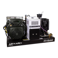
Why does the flywheel rotation slow down on a Vanair AIR N ARC RELIANT 250?
- BbushkevinSep 9, 2025
If the flywheel rotation slows down on your Vanair Power Supply, the belt(s) may be slipping. Try re-tensioning or replacing the belts.

Why does the flywheel rotation slow down on a Vanair AIR N ARC RELIANT 250?
If the flywheel rotation slows down on your Vanair Power Supply, the belt(s) may be slipping. Try re-tensioning or replacing the belts.
What to do if Vanair Power Supply has high AC voltage?
If your Vanair Power Supply has high AC voltage, adjust the speed control.
How to troubleshoot no welder output on a Vanair Power Supply?
If the DC welder on your Vanair Power Supply has no output, replace the welder field fuse.
What causes Vanair AIR N ARC RELIANT 250 compressor capacity to be too low?
If the compressor capacity of your Vanair Power Supply is too low to accommodate demand, consider substituting a larger capacity compressor system. Check for obstructions to air filter vents. Re-situate and adjust belt tension, or replace the belt if necessary. The engine governor might be stuck, so free it and lubricate if necessary. Also, the unloader valves might be sticking or faulty.
| Brand | Vanair |
|---|---|
| Model | AIR N ARC RELIANT 250 Series |
| Category | Power Supply |
| Language | English |
Details changes in specifications affecting the Air-N-Arc 250 model.
Diagram illustrating engine and drive parts with numerical key.
Explains Vanair's limited warranty, coverage periods, and exclusions for its equipment.
General safety information, including warnings, cautions, and international symbols.
Details hazards associated with arc welding, such as electrical shock, fumes, and sparks.
Covers hazards related to the engine, including battery, fuel, and exhaust systems.
Details hazards associated with compressed air systems, including pressure and trapped air.
Covers additional symbols for operation and maintenance, and general precautions.
Includes California Proposition 65, safety standards, EMF info, decals, and fluid disposal.
Provides a general description and visual guide to the machine's major components.
Details components of the compressed air system, including the compressor unit, intake, and valves.
Details the engine, its components, and related systems like fuel and oil.
Describes the AC generator, its type, and basic features.
Details the functions of controls on the instrument panel and their operation.
Provides specifications for the welder, generator, and engine components.
Details specifications for the air compressor system, including capacity and oil.
Lists unit weight, dimensions, and torque specifications for bolts.
Specifies acceptable testing output ranges for various functions.
Instructions for inspecting the machine package upon receipt for shipping damage.
Steps for preparing the machine package before installation.
Guidelines for preparing the service body for mounting the machine.
Procedure for securely mounting the machine package.
Diagrams illustrating installation and dimensions for proper placement.
Overview of controls, indicators, and general operating principles.
Detailed procedures for starting and shutting down the engine safely and correctly.
Explains how engine speed is controlled based on system demands.
Guides on operating the welder in different modes (CC, CV) and with various accessories.
Instructions for operating the AC generator, including output limits and breaker reset.
Details on operating the continuous-run air compressor and its control systems.
Procedures for connecting, operating, and disconnecting the battery booster/charger.
Guidelines for operating the machine in cold, hot, or high altitude environments.
Overview of maintenance importance, schedule, and related procedures.
Detailed table outlining maintenance tasks and intervals for the machine.
Information on ordering parts and detailed procedures for replacement and adjustment.
Procedures for inspecting and replacing the compressor air filter element.
Instructions for checking and changing the compressor oil.
Details on maintaining unloader valves susceptible to contamination.
Procedures for inspecting and maintaining compressor head valve assemblies.
Instructions for adjusting the compressor's cut-in and cut-out pressure settings.
Guidance on adjusting engine speed, with contact information for service.
Detailed procedures for accessing, replacing, and tensioning compressor and generator drive belts.
Procedure for draining moisture accumulation from the air tank.
Covers engine maintenance tasks, including air filters, oil, fuel filters, and coolers.
Guidance on locating, identifying, and replacing system fuses and circuit breakers.
Instructions for intermittent use and long-term storage of the machine.
General troubleshooting advice and information on condensation issues.
Common engine faults, possible causes, and corrective actions.
Common compressor faults, possible causes, and corrective actions.
Common DC and AC generator faults, possible causes, and corrective actions.
Introduction to diagrams and reference to measurement specifications.
Detailed wiring diagram for the Air N Arc 200 Series system.
Wiring diagram specifically for switches and lights on the control panel.
Flow schematic illustrating the compressor system's operation.
Instructions on how to order parts, including serial number requirements.
Illustrates major system assemblies and lists recommended spare parts.
Illustrated breakdown of the compressor unit and its associated parts.
Illustrated breakdown of the machine's frame components.
Illustrated breakdown of the instrument panel and its components.
Illustrated breakdown of the engine and drive system parts.
Illustrated breakdown of the belt guard assembly components.
Illustrated breakdown of the electrical system components.
Illustrated breakdown of the fuel tank assembly and its components.
Illustrated breakdown of the control assembly components.
Diagrams showing locations of safety and warning decals on the machine.
Chart detailing starting watts for various electric motor types and horsepowers.
Guide for selecting appropriate extension cord gauge based on load and length.
Lists wattage requirements for common electrical units and tools.
Details air consumption (CFM) requirements for various air tools.
List of optional accessories and their part numbers for the Air N Arc 200.
Recommendations for proper hose installation to ensure system integrity and longevity.
Step-by-step guide for correct electrode ignition and striking techniques.
Illustrates functional sequences of the pressure system control for operational clarity.
Explains the purpose of the log and provides guidance on service scheduling.
Forms for recording service points, dates, and parts replaced.
 Loading...