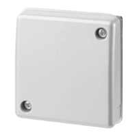
The GM730 has a fixed temperature range lower -15° C to +85° C.
The GM760 & GM775 have default settings the same as the GM730
but are adjustable by 1° C to lower and upper limits of -40°C and 85
°C. If these limits are exceeded then an alarm is indicated. (not prac-
tical to perform on site)
Table 7-2: Commissioning & test procedure
7.3 Staged commissioning
It is possible to commission seismic detectors using a power source and a multi-meter. This option
may be useful for staged commissioning or when permanent supplies or commissioning tools are not
yet available.
7.3.1 Staged commissioning procedure
1. Power up the device, observing the correct polarity and leave for 30 seconds.
The internal LED will pulse for 10 seconds to confirm that the correct power is applied. The
LED is not available on the GM710 version.
2. Verify that the correct operating radius and material type are selected via the DIP switches or
use the SensTool, if available to select.
3. Use a multi-meter at terminal 1 (0 V) and at the test point, which is a gold coloured solder pad,
just to the left hand side of the terminal strip.
The following voltages will determine the status of the detector.
Quiescent level = circa 0 to 0.3v DC
Detection of the integration signal will increase the voltage to = 1v DC, this voltage will
continue to increase, in direct proportion to the strength and/or duration of the integration
signal. The integration alarm can be generated by use of the hand held test tool or by
scratching the base plate of the detector with a screwdriver.
Activating the GMXS1 or GMXS5 will increase the voltage to around 2.7v DC.
The LED beside the test point on the detector illuminates as visual confirmation for all
detectors except the GM710.
Activating the shock alarm will increase the voltage to around 2.7v DC when the required
impact is detected.
The LED beside the test point on the detector illuminates as visual confirmation but
recording the voltage and providing the required impact may be difficult to achieve.
Alarm threshold (w/o load) = 3v DC. Note that this 3v DC reading only reflects the
integration alarm and does not depict a drill alarm, temperature alarm and/or a shock
alarm.

 Loading...