Seismic Detectors Application Guide
3 Installation - Detectors
It is essential that the GM7xx detectors are installed correctly to provide the optimum performance
from the detector and to ensure that the required signals from the protected surface are transmitted to
the detector.
3.1 Drill template
A drill template is provided with each detector to assist with the correct method of securing the detec-
tor to the protected surface.
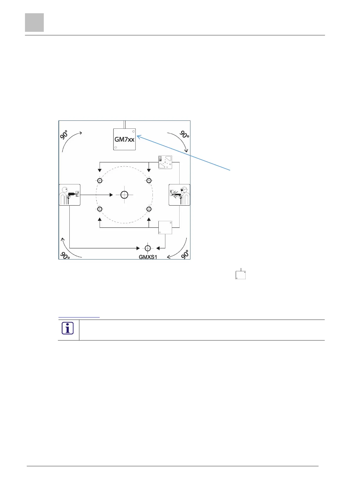
Figure 3-1: GM7xx drill template
a) The cable access point for the detector is depicted by the symbol , which shows the cable ac-
cess at the top of the detector. The drill template can be turned through 90, 180 & 270⁰ to have the
cable access from the top, right, bottom or left side.
There is a 1:1 scale copy of the drill template located in Appendix 1: Drill template GM7xx.
The drill templates are also available as a download from the Vanderbilt Seismic microsite on SPIAP.
www.spiap.com
Before installing a detector, Vanderbilt recommend that you consult the guidelines for instal-
lation in this document.
For more information, see Section 5.4 Installation guidelines.
3.2 Installation methods
This section contains useful information on the three main methods of detector installation.
Direct installation on steel
Indirect installation on steel
Installation on concrete
3.3 Detector installation onto flat steel surface
Use this method to install a detector on a flat and even steel surface.
Remove all paint or grease from the steel surface to ensure that the detector has the optimum metal to
metal contact between the rear of the detector and the protected surface.
To mount the detector directly onto the steel surface, drill two holes to secure the detector, and one
hole to secure the GMXS1 test transmitter, if required.
a) Cable access indicator

 Loading...


