WARNING - Before starting to install and work with this device, please read
the Safety Instructions.
EC Declaration of Conformity
Hereby, Vanderbilt International (IRL) Ltd declares that this radio equipment type,
is in compliance with all relevant EU Directives for CE marking. From 20/04/2016 it
is in compliance with Directive 2014/30/EU (Electromagnetic Compatibility
Directive) and Directive 2014/35/EU (Low Voltage Directive). From 13/06/2016 it is
also in compliance with Directive 2014/53/EU (Radio Equipment Directive).
The full text of the EU declaration of conformity is available at:
http://pcd.vanderbiltindustries.com/doc/SPC
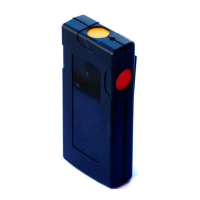
Introduction to the IPAW8-10 Wireless Personal Alarm
The IPAW8-10 Wireless Personal Alarm (WPA) is a belt clip panic device with
three configurable buttons.
Enrollment and testing
To enrol the WPA into the control panel, follow the instructions of the
corresponding installation/configuration manual.
The WPA is supplied with the battery and when installed, the unit is ready to be
enrolled.
1. Press a key on the WPA to verify that the transmit LED lights.
2. Make sure that the control panel responds as programmed and as stated in
the installation/configuration manual.
3. Repeat the test at locations where the WPA will be operated under normal
use, in order to ensure the wireless transmission is not blocked by any walls or
large objects, or affected by structural materials.
Functions (Fig. 1)
Programmable transmission button which can be configured
to be used solely or in combination with the other buttons to
activate an assigned function; (e.g. panic, holdup, suspicion,
trigger).
When used in combination they must be pressed
simultaneously for 2 seconds to activate the function
Programmable transmission button similar to green button.
Activates an assigned function
(e.g. panic, holdup, suspicion, and trigger).
You can clip this to a belt or remove to attach under a desk.
Also reversible.
Transmission
LED Indicator
Lights up for button presses when transmitting.
Programmable transmission button similar to green button.
Activates an assigned function
(e.g. panic, holdup, suspicion, and trigger).
All messages include battery state (normal or low). The
panel raises an alert if the battery power is low.
Reversible Belt Clip (optional, fig. 2, 3, 5, 6)
The belt clip can be fitted in the normal position or upside down, according to
individual preferences. To reverse the position of the clip, remove the screw
holding the belt clip, lift the tab under the clip, slide the clip down, reverse the
position and reattach the screw.
Supervision signaling (Fig 2-6)
The WPA may be configured to send periodic supervision signals.
To enable this feature on the WPA:
1. Remove the belt clip to provide access to the battery. (See section on Battery
Exchange).
2. Using a tweezers, insert a jumper onto the two pins located beside the battery
(fig 4, JP2).
3. Replace the belt clip.
Note: To operate supervision for each WPA, this function also needs to be
enabled on the panel. For configuration instructions, please refer to the SPC
Configuration Manual. If the panel does not get a supervision signal, an alarm is
raised that is displayed on the keypad and logged.
If supervision is not enabled, the WPA sends out a supervision message about
every 24 hours to transmit the WPA battery status to the panel.
Battery exchange (Fig. 2-6)
In order to change the battery, remove the screw holding the belt clip, lift the tab
under the clip, and slide the clip down to have access to the battery holder.
Cautiously remove the old battery and replace it with a new one and close the
housing again. In figure 5 and 6, the belt clip is closed in the reverse position.
Insert the battery in the battery holder making sure the polarity is correct (+)(-)
Risk of explosion if battery is replaced by an incorrect type.
Clean the WPA only with a soft cloth or sponge moistened lightly with a mixture
of water and mild detergent and wipe it dry immediately. Also never use solvents
such as kerosene, acetone or thinner. The use of abrasives of any kind is not
recommended.
Technical data
Unique ID serial number – 24 bit
Low battery indication below 3.0V
Battery Lithium 3.6 V, size 1/2AA, 1 Ah
(type Tadiram TL5902)
0.100 kg (including belt clip and battery)
115mm x 55mm x 35mm (including belt clip)
Polycarbonate with reversible belt clip
WARNUNG Lesen Sie vor der Installation und Verwendung dieses Geräts die
Sicherheitshinweise.
EG-Konformitätserklärung
Hiermit erklärt Vanderbilt International (IRL) Ltd, dass dieser Funkgerätetyp den
Anforderungen aller relevanten EU-Richtlinien für die CE-Kennzeichnung
entspricht. Ab dem 20.04.2016 entspricht er der Richtlinie 2014/30/EU (Richtlinie
über elektromagnetische Verträglichkeit) und der Richtlinie 2014/35/EU
(Niederspannungsrichtlinie). Ab dem 13.06.2016 entspricht er außerdem der
Richtlinie 2014/53/EU (Richtlinie über Funkanlagen).
Der vollständige Text der EU-Konformitätserklärung steht unter
http://pcd.vanderbiltindustries.com/doc/SPC zur Verfügung.
SchwedenFunknotrufgerät IPAW8-10 – Einführung
Das Funknotrufgerät IPAW8-10 ist ein persönliches Alarmgerät mit drei
konfigurierbaren Tasten, das am Gürtel getragen werden kann.
Anmelden und Testen
Um das IPAW8-10 bei der Zentrale anzumelden, die Anleitungen des
entsprechenden Handbuchs befolgen.
Das Funknotrufgerät wird mit Batterie geliefert und kann sofort nach der
Installation angemeldet werden.
1. Eine Taste auf dem Notrufgerät drücken, um zu überprüfen, ob die Sende-LED
leuchtet.
2. Sicherstellen, dass die Zentrale wie programmiert und wie im
Installationshandbuch angegeben reagiert.
3. Den Test an Orten wiederholen, an denen das Notrufgerät im normalen
Einsatz verwendet wird, um sicherzustellen, dass die Funkübertragung nicht
durch Wände oder große Gegenstände blockiert oder durch Baumaterialien
beeinträchtigt wird.
Funktionen (Abb. 1)
Programmierbare Sendetaste, die so konfiguriert
werden kann, dass sie allein oder in Kombination mit
anderen Tasten die zugewiesene Funktion aktiviert
(z. B. Panik, Bedrohung, Misstrauen, Trigger).
Wenn die Tasten in Kombination verwendet werden,
müssen sie gleichzeitig 2 Sekunden lang gedrückt
werden.
Programmierbare Sendetaste ähnlich der grünen
Taste. Aktiviert eine zugewiesene Funktion
(z. B. Panik, Bedrohung, Misstrauen, Trigger).
Mit diesem Clip kann das Notrufgerät an einem Gürtel
befestigt werden. Der Clip kann entfernt werden, um
das Gerät unter einem Tisch anzubringen. Der
Gürtelclip kann auch umgedreht angebracht werden.
Leuchtet auf, wenn die Tasten zur Übertragung
gedrückt wurden.
Programmierbare Sendetaste ähnlich der grünen
Taste. Aktiviert eine zugewiesene Funktion
(z. B. Panik, Bedrohung, Misstrauen, Trigger).
Alle Nachrichten beinhalten den Batteriestand (normal
[normal] oder niedrig [low]). Die Zentrale löst einen
Alarm aus, wenn der Batteriestand niedrig ist.
 Loading...