VM-5500 Operator’s Manual
Introduction | Rev 0418.1
1.3 Installation
Your VM-5500 comes with a RAM 1 ½” Mounting Ball. Any RAM Mount 1 ½” fixtures will adapt to your
monitor.
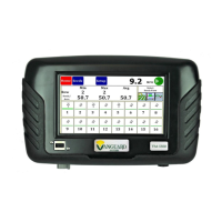
Figure 1 Monitor Mounting
Install the RAM-238-U 1 ½” Ball supplied with your console by removing the two screws from the rear of
the unit and use them to attach the ball.
Any RAM configuration may be used to attach your console to a convenient location in your cab. If you
need a base mount, see the above for more options. See your local dealer for brackets and arms that
are available, or visit www.agdirectusa.com to purchase online.
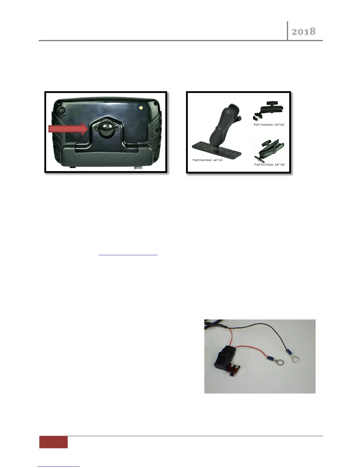
1.4 Monitor and Power Connections (Harness 647103)
Route the power leads of the main harness to the battery. Allow some slack to tie the harness off to a
secure location in the cab to provide strain relief and for the protection of the harness.
The monitor operates on 12 VDC only. The red (Fused)
lead should be connected to the positive battery terminal
and the black lead should be connected to the negative
battery terminal.
There is a short two pin Deutsch connector at the monitor
end of the power cord. This is for connecting the
optional Visual Alarm Light (Part No. 647105)
 Loading...