Do you have a question about the Vantex Sbach 300 73" 30cc and is the answer not in the manual?
This is an instruction manual for the VANTEX Sbach 300-73" 30cc, a high-performance radio-controlled aerobatic model airplane. The manual provides comprehensive instructions for assembly, setup, and preflight checks, ensuring a safe and thrilling experience for hobbyists.
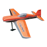
The Sbach 300 is designed for high-performance scale aerobatics, offering an exhilarating flying experience. Its construction from high-quality balsa and plywood ensures a lightweight yet strong airframe, capable of withstanding the stresses of aerobatic maneuvers. The model features a foam brace on the back of the fuselage for added structural integrity and a hidden switch hatch design for a clean aesthetic and easy access. Enhanced cowling mounting design and a complete hardware package, including an antenna tube, are also part of its features. The airplane boasts a nice color scheme with professional covering, making it visually appealing both on the ground and in the air.
Before starting assembly, it is crucial to inspect all parts for damage or missing components. Any wrinkles in the covering can be smoothed out with a heat gun or covering iron, taking care around overlapping colors. The assembly process begins with the aileron servo installation, where the covering is carefully removed from the servo opening, and a servo extension is plugged in. A weight tied to a string is used to guide the servo lead through the wing. The servo is then secured, ensuring the servo arm is parallel with the hinge line when in the neutral position. This process is repeated for the remaining wing panel.
Next, the aileron control horns are installed. The aileron is taped to the wing, and a square is used to mark the position for the control horn, aligning with the outer hole in the servo arm and the trailing edge of the wing. A second mark is made rearward from the aileron bevel to pinpoint the exact control horn position. After removing the ailerons and cleaning any tape residue, a hole is carefully drilled through the aileron at the marked position, taking precautions to prevent splitting the wood. A hardwood block is located below the sheeting, so drilling perpendicular to the centerline of the aileron is important. The control horn screw is then plugged through the hole from the top of the aileron and secured with a nut.
Hinging and sealing the control surfaces is a critical step for precise control response. The hinges, predrilled in the control surfaces, must be securely bonded. Both ends of the hinges are sanded to improve epoxy adhesion. Thirty-minute epoxy is mixed and applied into the hinge pockets in the aileron leading edge. Hinges are installed until the hinge pin center is flush with the leading edge, and excess epoxy is wiped away. It is important to ensure the hinge pivot pins are parallel and flush to the aileron leading edge. After the epoxy cures, the hinges are worked throughout their full motion to break free any excess epoxy.
The aileron linkage installation involves screwing a molded swivel link with linkage onto the control horn screw until a specific distance from the aileron surface is achieved. The linkage length is adjusted so the ball link aligns with the outer hole in the servo arm when the aileron is neutral and the servo arm is centered. The ball link is then attached to the servo arm with a screw and nut, using threadlock.
Wing installation begins by checking and carefully removing the covering from the openings for the wing tube, servo leads, and pins inside the fuselage. The wing tube is slid into one wing panel, and then the wing (with tube) is slid into the fuselage. Servo leads are passed into the fuselage, and anti-rotation pins are slid into their respective holes. It may be necessary to slightly enlarge the holes in the fuselage for the anti-rotation pins. The remaining wing panel is then carefully slid onto the wing tube, ensuring a snug fit without gaps, and secured with wing screws.
Stabilizer installation follows a similar pattern. The covering is removed from the elevator servo arm opening at the bottom of the stabilizer, and the elevator servo is installed. The elevator servo is centered using the radio system, and a servo arm is installed. The technique for installing control horns in the elevators is similar to the aileron control horn installation. Marks are made for the control horn position, and a hole is carefully drilled through the elevator, again taking care to prevent splitting the wood. The control horn screw is plugged through the hole from the top of the elevator and secured. One section of a hinge is cut off to clear the tube installed in the elevator. Elevator hinges are then glued in place using the same techniques as the ailerons, with shortened hinges installed towards the root of the stabilizer. The elevator linkage is installed, and the stabilizer is secured with screws at the bottom.
Rudder installation involves checking and removing the covering from the rudder cable opening in the fuselage. The rudder servo is installed on the right side of the servo tray, ensuring the servo arm is perpendicular to the fuselage centerline when neutral. A straight line is measured from the rudder servo arm to the opening, and an extension line is marked on the rudder. A second mark is made rearward from the rudder bevel to determine the control horn position. A hole is carefully drilled through the rudder at the marked position, perpendicular to the rudder centerline. The threaded rod of the rudder control horn is put through the hole and secured with nuts, adjusting its position to ensure equal length on both sides. The molded swivel link with linkage is screwed onto the threaded rod, ensuring the rudder cable does not hit the fuselage opening.
Tail wheel installation involves installing the tiller arm to the bottom of the rudder with screws. The tail wheel is positioned at the rear of the fuselage, and mounting screw positions are marked through the tail wheel bracket. The bracket is removed, pilot holes are drilled, and the tail wheel bracket is secured with screws, using a hardwood plate in the fuselage for firm tightening. Thin CA glue can be wicked into the holes to strengthen the threads before reinstalling the screws. Finally, springs are used to hook up the tiller arm to the rudder with the tail wheel.
Landing gear installation requires installing the axles into the landing gear and securing them with an adjustable wrench and nuts. A washer, wheel, and wheel collar are installed onto the axle, potentially requiring drilling the wheel hole to fit. The wheel pant, with pre-installed blind nuts, is slid into position and secured to the landing gear with two screws, using threadlock to prevent loosening. The landing gear is then installed to the fuselage with four screws and lock washers.
Receiver, battery, and fuel tank installation involves securing the receiver to the battery tray with foam and rubber bands or hook and loop straps. The receiver battery is wrapped in foam and secured to the battery tray. The fuel tank is assembled correctly, ensuring gas-compatible stopper and fuel tubing are used. Foam is placed on the tank compartment floor, and the tank is secured with rubber bands or hook and loop straps. The hidden switch hatch on the side of the fuselage is opened, the receiver switch is mounted, and the hatch door is closed.
Engine and cowling mounting involves collecting necessary items for the specific engine. For a 26cc gas engine, the vertical and horizontal base lines on the firewall are used to mark the distance for the four engine standoff screws. Holes are drilled in the firewall, and four screws are installed from the back, with optional epoxy glue. The engine is installed using machined aluminum standoffs, screws, and lock washers. The throttle servo is installed with its arm, a hole is drilled in the firewall for the throttle linkage, and the linkage is attached to the servo arm and throttle. The exhaust pipe is installed, and the ignition module is secured to the engine box, connecting it to the engine. The switch for the ignition is installed in the switch hatch. The ignition battery is secured inside the fuselage with a hook and loop strap and foam to prevent vibration damage. Fuel lines are attached from the fuel tank to the carburetor and routed out the bottom of the cowling. Necessary cutouts are made in the cowling to clear engine components and allow cooling air to pass through. Finally, the cowling is slid and locked to the fuselage, secured with a screw, and the propeller and spinner are mounted. To access the cowling mounting screw, the hatch needs to be opened by removing its screws.
For radio setup, a 7-channel or greater computer radio is highly recommended for features like flaperon mix, electronic aileron differential, dual elevator mixing, and independent travel and trim adjustments. Each servo is plugged into its own channel. Recommended control throws are provided for aileron, elevator, and rudder for both standard and 3D settings.
Correctly balancing the aerobatic model is crucial for performance. The recommended center of gravity (CG) range is measured back 30%-33% of the whole wing root's length from the leading edge and marked at the wing tip.
Preflight checks are essential for safety. Maintaining proper mechanical advantage on all control surface linkages is vital. The radio installation, control surface movement, and engine transitions from idle to full throttle must be checked. All control horns, servo horns, and clevises must be secure. Never attempt full throttle dives, as large models perform more like full-size airplanes and can fail if flown too fast. Hardware checks include double-checking setscrews in control horns and using threadlock on metal-to-metal fasteners. Adequate receiver batteries (6-volt, minimum 2700mAh, 3000mAh for super high torque servos) are necessary. A range check of the radio system should be performed before the initial test flight and periodically thereafter. The voltage of on-board packs should always be checked with an ESV with a 1-amp load before each flight, and packs should be recharged if questionable.
The manual emphasizes that this is a sophisticated hobby product, not a toy, requiring caution and common sense. It must be operated responsibly to avoid injury or damage. It is not intended for children without adult supervision. The model is controlled by a radio signal subject to interference, so maintaining a safe distance is advisable. Operating in open areas away from traffic and people, avoiding populated areas, and ensuring transmitter batteries are not low are crucial safety measures. Following directions for all equipment, keeping chemicals and small parts out of reach of children, and avoiding moisture exposure to electronics are also important.
The product comes with a limited warranty covering defects in material and workmanship at the date of purchase, but it does not cover cosmetic damage, damage due to acts of God, accidents, misuse, abuse, negligence, commercial use, modification, improper installation, operation, or maintenance. The warranty is limited to the original purchaser and does not cover consequential, incidental, or collateral damage. The company reserves the right to inspect equipment and make repair or replacement decisions at its sole discretion. The consumer's exclusive remedy is repair or replacement. The company assumes no liability for damage or injury resulting from use, setup, final assembly, modification, or misuse. If the purchaser is not prepared to accept this liability, they are advised to return the product in new and unused condition.
| Construction Material | Balsa and plywood |
|---|---|
| Wingspan | 73 inches |
| Engine | 30cc |
| Type | RC Airplane |
| Radio | 6+ channel |
| Servos | 6 high torque servos |