* Ø 35mm steam pipe : non-standard pipe required which has reverse slope and end outlet Ø15mm.
Pipe in-duct length 300mm – Pt No. M520115, 450mm – Pt. No. M520116, 600mm – Pt. No. M520117, 750mm – Pt. No.
M520118, 900mm – Pt. No. M520119, 1050 mm – Pt. No. M520120.
* Ø 54mm steam pipe : non-standard pipe required which has reverse slope and end outlet Ø15mm.
Pipe in-duct length 650mm - Pt No. M520078
Pipe in-duct length 900mm - Pt. No. M520079
Pipe in-duct length 1400mm - Pt.No. M520080
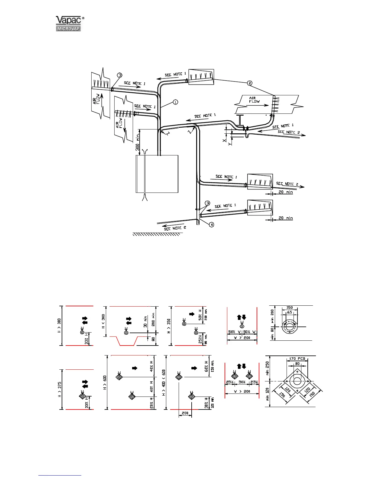
1 Steam pipe to have a
minimum slope from the
horizontal of 7° or 12% to
allow the condensate to drain
back to cylinder or trap.
NO HORIZONTAL RUNS.
NO 90° ELBOWS.
2 Water condensate to slope at
10° or 18% from horizontal for
condensate to drain back to
drain point.
3 Steam pipes horizontal
mounted must discharge
vertically upward.
Vertical mounted steam pipe must
discharge horizontally facing
upstream airflow.
5 If the total pressure within the duct
air flow exceeds 2000 Pa and the
static pressure is below 2000 Pa
then the probe may face horizontally
at right angles to the air stream.
1 Insulated Steam Pipe
2 Steam Distribution Pipe
3 Hose clip
4 Condensate Separator
X = 60 minimum height for a maximum negative
pressure of –600 Pa.
Y = 220 minimum height for a maximum positive
pressure of 2000 Pa.
Z = 250 minimum Radius for 35 ∅ pipe,
500 minimum Radius for 54 ∅ pipe.
35 ∅ 1 Steam Pipe 35 ∅ 1 Steam Pipe 35 ∅ 2 Steam Pipes
1 Steam pipe
54 ∅ 1 Steam Pipe 54 ∅ 2 Steam Pipes 54 ∅ 2 Steam Pipe
4 x 6.4 ∅ Fixing Holes on
 Loading...