3
Installation.
Positioning the Vapac
Do’s
Do mount the unit as close to the steam distribution pipe(s)
as possible.
Do mount the unit at a height convenient for reading the
display window.
Do ensure adequate side access to the electrical section
(min 1000 mm).
Do ensure adequate service access to the front of the unit
(min 1000 mm).
Do ensure adequate service access below the unit (min 300
mm).
Do ensure that the holes above the airgap between the
electrical and the steam sections remain unobstructed to
allow a free flow of air.
Do use the marking on the side of the carton as a template
to mark the mounting hole positions.
Do remove the cylinder, if necessary, to access the
mounting holes in the back of the steam section.
Do use M6 projecting type wall bolts or equivalent to mount
the unit in position.
Do mount units with RDU’s so that steam pipe discharge is
above head height.
Do leave minimum 150mm between the top of an RDU and
the ceiling.
Don’ts
Don’t mount the unit close to sources of strong electro-
magnetic emissions e.g. variable speed lift motor drives,
kVa transformers etc.
Don’t mount the unit in an unventilated enclosure.
Don’t mount in a position requiring ladder access to the
unit.
Don’t mount the unit behind a false ceiling or other situation
where an unusual malfunction (e.g. water leak) would
cause damage.
Don’t mount the unit in an area which will be hosed down.
Don’t install the unit where the ambient temperature can
exceed 35
o
C.
Don’t mount the unit inside a cold-room or other place
where temperature and humidity conditions can cause
condensation on electrical components.
Don’t mount the unit where the sound of a contactor
opening/closing and water flow in a pipe would be
unacceptable e.g. libraries, private apartments, etc.
Don’t position an RDU to discharge directly over
exspensive equipment, desks or stored materials.
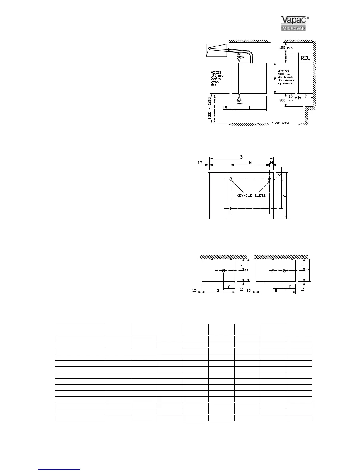
Dimensions in mm and Service Weight in Kg.
Positioning and Dimensions of the Vapac
Fig 1
Mounting Hole Positions.
Fig 2
Steam Outlet Positions
Microvap model V4
VP4
V8
VP8
V15
VP15
V30
VP30
V40
VP40
V40L
VP40L
V60
VL60
V80
VP80
A 500 630 675 800 800 800 800 800
B 380 380 435 538 538 645 645 857
C 263 263 298 384 384 500 500 384
D 182 182 182 - - - - -
F 159 159 175 206 206 266 266 212
G 112 112 136 190 190 195 195 175
H - - - - - 110 110 350
K 38 38 38 38 38 38 38 38
L 478 478 516 643 643 643 643 643
M 165 165 203 305 305 406 406 610
N 38 38 38 47 47 47 47 47
UNIT Kg. 25 25 30 55 55 90 90 97
RDU Kg. 8 8 12 - - - - -
RDU & Transformer 9.5 9.5 16.5 - - - - -
Fig 3
 Loading...