Installation
Varec, Inc. 45
pattern, and coupling of Varec accessories mates with the sheave drive elbow. Each mating
auxiliary unit has a slotted coupling that engages the drive pin on the sprocket sheave.
Mate the accessory with the sprocket sheave drive. Use the hex head cap screws and
washers to attach the accessory unit to the drive elbow.
Refer to the manual for the accessory unit, if installed, and check out the operation of the
accessory as appropriate.
Note The use of auxiliary units not manufactured or supplied by Varec will void any
Varec warranty and will relieve Varec of any obligation to service the product under war-
ranty.
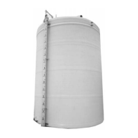
17. Install the gaugeboard and indicator. Refer to the appropriate tank configuration.
18. Set indicator at measured product level.
19. Adjust the tape/cable tension until the float barely lifts from its natural floating position,
then crimp the cable connector.
20. Tie a line to the indicator.
21. Slowly pull down on the indicator and lift the float to the top of the tank. Travel should not
produce noticeable binding. Slowly lower the float to the product level. Check that any
installed accessory performed properly during this test.
Caution Do not allow the float to fall to the surface of the product. Damage may result.
22. Refer to appropriate tank configuration to set the indicator at the full tank position, then
use the hand gauge measurement to recheck the current product level.