Liquid Level Indicator
48 Installation and Operations Manual
The tape segment attaches to the float. Position the tape/cable splice below the auxiliary
drive elbow with the float at the bottom of the tank.
5. Seat the perforated tape portion of the tape/cable combination on the sheave sprocket
and thread it through the indicator connector pipe.
6. Attach the auxiliary unit to the adapter flange.
7. Attach the auxiliary unit with adapter flange to the drive elbow ensuring that the sprocket
drive pin engages the slotted coupling of the auxiliary unit.
8. Refer to the auxiliary unit manual for operation and checkout procedures.
9. Refer to the appropriate tank configuration to complete the installation.
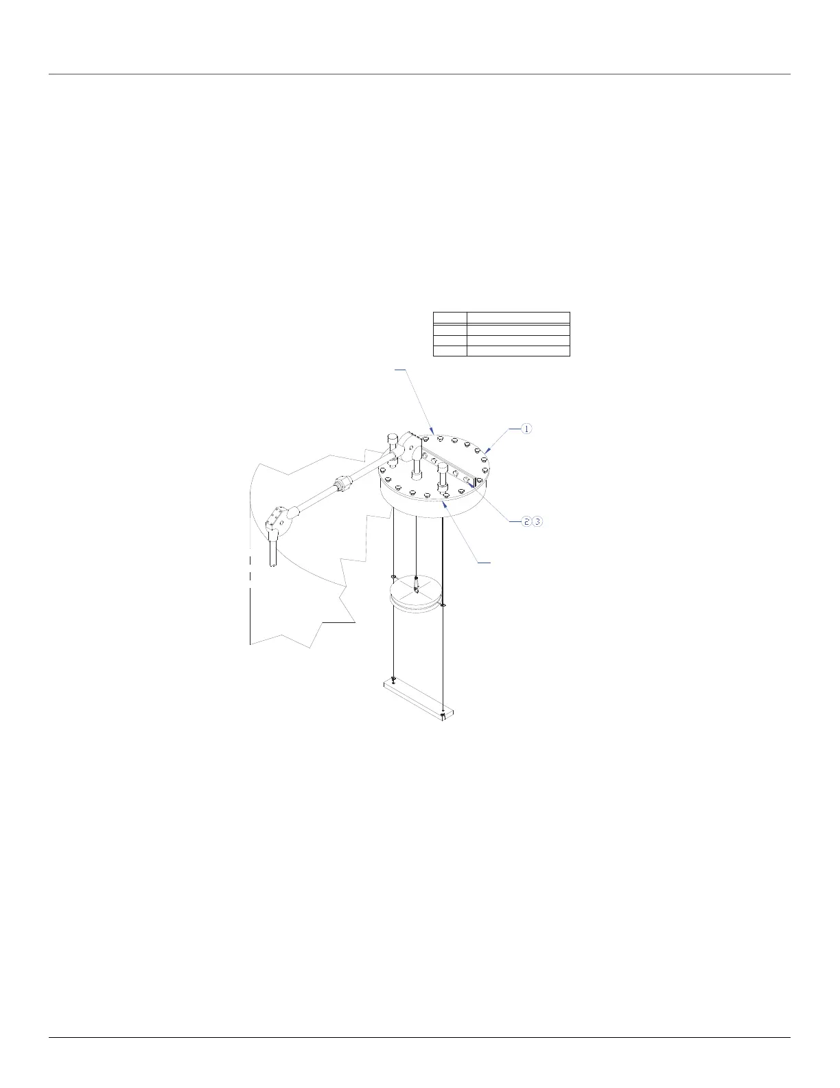
Figure 21: API 20/24-Inch Manhole cover Installation
Whesoe Varec Figure 226
Manhole Cover
(Standard for 20 inch API-650.
Other sizes available on
special order.)
Manhole cover gasket
and mounting hardware
furnished by customer.
COVER PLATE ASSY.
ITEM
1
3
2
DESCRIPTION
HEX NUT
HEX BOLT