5. TECHNIQUE OF CONTROLLING THE JIKOV ENGINE WITH AUTOMATIC CENTRIFUGAL
CLUTCH
Coupling of the centrifugal clutch depends on engine rotations. This is why steering of this type of engine requires
technique which differs from that applied in controlling for example an engine with multiple-disk clutch. Two working
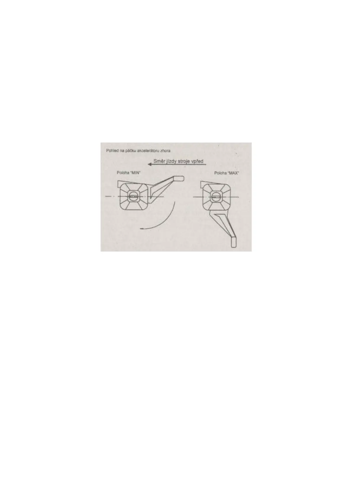
positions of accelerator lever are illustrated in Figure 5:
– " MAX " : with accelerator lever in this position the engine has maximum output and the clutch is in full
engagement (provided that the engine is not overloaded and is not runnig at low rotations)
– " MIN " : with accelerator lever in this position the engine has no-load speed and the clutch is out of
engagement. Engine working speed is between 2500 to 4800 RPM. Use maximum engine rotations so that clutch
slippage and hence its damage cannot occur.
Engine rotations should be increased fast so that the engine has higher speed than the rotations at which the clutch gets
into engagement in order to prevent clutch slippage. Centrifugal clutch has a smooth engagement at a rapid increase of
engine rotations.
Figure 5: Working positions of accelerator lever
Pohled na páčku akcelerátoru zhora View of the accelerator lever from above
Směr jízdy stroje vpřed Direction of machine drive forward
Poloha „MIN“ „MIN“ Position
Poloha „MAX“ „MAX“ Position
TECHNIQUE OF CONTROLLING THE SAFETY IGNITION SWITCH
Safety ignition switch Model BVA - 96 meets the standard of safety ignition switches used by manufacturers of small
gardening technology abroad. This switch ensures switching of engine ignition system and hence stoppage of engine
operation immediately after the operator has left its site in a critical situation or for putting the machine out of operation.
The safety ignition switch has three functional positions as follows:
Position 1 is to be used for starting the engine, setting engine speed or for a short-time putting of the machine out of
operation while the engine is still on.
At this position of the safety ignition switch, always shift on neutral gear on the gearbox or switch off the clutch of
travel wheels and disconnect the drive of working implements!
Position 2 is to be used for machine operation. If the machine is in operation, the wire dog has to be always released!
Position 3 is to be used for switching the engine off in critical situations or for putting the machine out of operation. The
engine will switch off after the lever of the safety ignition switch on the left handlebar rail has been released. Putting the
hand away from the handlebar will do to stop the engine on the condition that the wire pawl is released.
 Loading...