The braking system must be monitored.
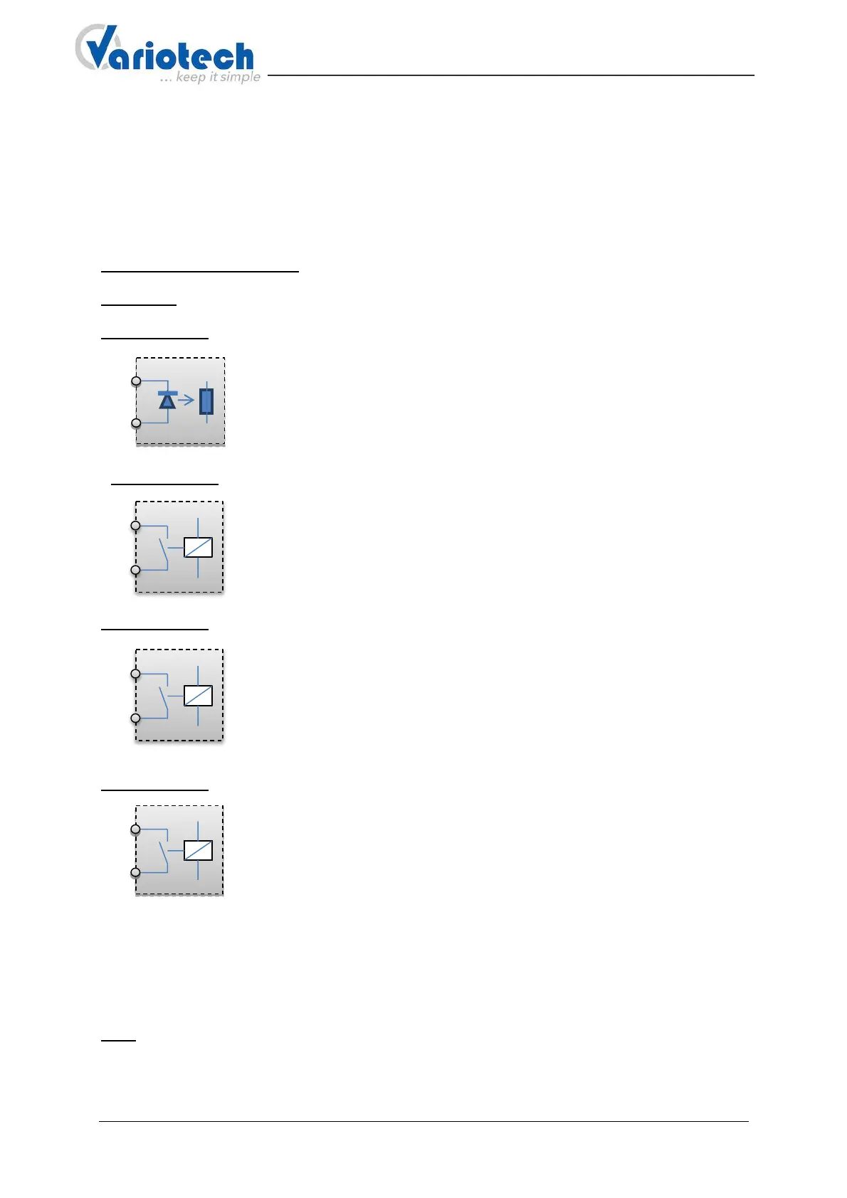
When the lift is in the station the unit must be in inoperative position and the feedback contact should
be closed (NC contact). This also allows a detection of a line interruption.
However, if only one normally open contact (NO contact) is present it can also be used.
• A normally closed NC contact must be connected to terminal 5, 6
• A normally open contact NO contact must be connected to terminal 4, 5
• If no feedback contact is present, the terminals 5, 6 must be bridged.
Terminal 7 (PLUS), 8 (Minus): connection power supply 24V DC (+/- 10%)
Terminal 9: connection protected earth.
Terminal 10, 11: connection for safety circuit and safety circuit feedback
with wide input voltage range:
This input automatically adjusts to the applied voltage
in a range from 24V to 230V AC / DC.
Terminal 12, 13: Safety relay contact.
This contact is used to test a door zone bypass circuit of the door switches and
is integrated in series in the bypass. If no bypass circuit is present the terminals
12 and 13 remain free. When leaving the door zone the contact is opened so
that the door switch can be tested without any interference from the bypass
circuit. The relay contacts have a switching capacity of 3A, 250V.
Terminal 14, 15: Safety relay contact.
This contact will be integrated in the safety circuit according to the schematic
diagram and serves to switch off the lift on the UCM error. To protect the
contacts of the safety relay and thus to increase the reliability, a fuse in series
with the contacts was implemented directly on the board.
The fuse has a value of 2.5 A.
The relay contacts have a switching capacity of 3A, 250V.
Terminal 16, 17: Safety relay contact.
This contact is for switching off the UCM-braking system and should therefore be
integrated directly in the circuit of the braking device.
The relay contacts have a switching capacity of 3A, 250V.
Note: Assuming that a connected coil with a suitable protective diode (freewheeling diode) is
connected, the relay outputs (terminal 12/13, 14/15, 16/17) switch a maximum DC voltage up to
24VDC, 1A.
Displays, signal transducer and switch:
LEDs: To view certain operating conditions 6 LEDs are available.
• 2 LED labeled with "Zone"
The LED indicates when the car is in a door-zone.
If both LEDs are lighted the car is within the door zone, otherwise it is outside the door zone
If only one LED is lighted a magnetic switch is defective and must be replaced.