Parts List
Assembly Instructions
1. Table Top (Small); 2. Table Top (Big)
3. Release Handle; 4. 1/4 -20 Bolt &Nut! 1 each"
5. Top Bracket Tube I 7. Top Bracket Tube II
8. Bracket Connecting piece; 9. Fixed Knob
10. Bolt Sleeve; 11. Bolt Plate; 12. 3/8 -18UNF Bolt;
13. 1/4 -20 Bolt! black" ; 14. 1/4 -10 Bolt! white" ;
15. Drawn Pipe ;16. Spacer; 17. Column Assembly;
18. Washer; 19. Triangle Knob;
20. Stand Pipe Stopper.; 21. Stand pipe . 22. Base
23. Caster with Lock! 2 each" ;
24. Caster without Lock! 2 each"
1. Table Top (Small)
2. Table Top (Large)
3. Release Handle
4. 1
/4" #20 Bolt & Nut (1 Each)
5. Top Bracket Tube 1
6. Top Bracket Tube II
7. Bracket Connecting Piece
8. Fixed Knob
9. Draw Pipe
10. Bolt Sleeve
11. Bolt Plate
12. 3/8" #18 UNF Bolt
13. 1/4" #20 Bolt (Black)
14. 1/4" #10 Bolt (Chrome)
15. Spacer
16. Column Assembly
17. Spacer
18. Triangle Knob
19. Stand Pipe Stopper
20. Stand Pipe
21. Base
22. Caster With Lock (2)
23. Caster Without Lock (2)
24 Outer Tube
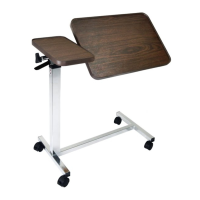
2. Place Trip Lever (3) with its curved side facing upwards on
Column Assembly (16). Ensure the Trip Lever sits on top of the
Trip Rod that is within the column. Secure with Bolt and Nut (4)
See Fig. 2.
1
. Remove
contents from packaging. Lay
Top
Boards
(1
&
2)
upside
down
on
flat
surface
with
Mounting
Tubes
(5
&
6) facing
upward. See Fig. 1. Set aside for use at Step 3.
3. Remove Triangle Knob (18), Spacer (17) and the Inner Tube (9)
from the Outer tube (24). See Fig. 3.
4. Insert Outer Tube (24) of the Column Assembly through
Mounting Tube (5) of the Short Top Board from Step 1. Then
insert Outer Tube through the Mounting Tube (6) on the
Large Table Top (2). Insert Inner Tube (9) through Mounting
Tube (6). Tighten Fixed Knob (18) and Spacer (17) into the
“Hole” on Outer Tube (24). See Fig. 4.
FIG. 1
1
2
5
6
FIG. 3
16
17
18
Indent
24
Page 1
Item #: M881
N-STCR-YYVM
Important Warnings
Please follow all instructions and warnings to avoid hazardous
situations that can result in property damage and/or patient/
resident/staff/caregiver injury and/or death.
Inspect the product for damage and loose hardware before each
use. DO NOT use the product if it appears to be damaged or
unstable and DO NOT modify the product in any way.
Assembly Precautions
This Overbed Table utilizes a high-tension spring loaded
mechanism to raise the table. DO NOT remove #13 Black
Screw and replace with the #14 Chrome Screw until table is
fully assembled. The table top will raise suddenly and cause
serious personal injury. DO NOT over tighten bolts, screws or
use power tools when assembling this product.
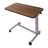
Deluxe Tilt-Top Overbed Table
FIG. 4
9
IMPORTANT NOTE!!!
It is normal to hear clanking
sounds when shaking or moving
the Column Assembly (16). This is
due to the movement of the trip
rod within the column. During
transport, sometimes the trip rod
may fall out of the column
assembly. Simply re-insert the trip
rod back into the column before
proceeding to the next step.
(Reminder: DO NOT remove #13
Black Screw from the column)
Ref no: M881N-STCR-YYVM Manual V3031518