7
Power supply cable
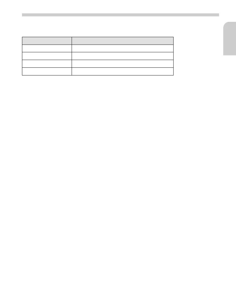
Cable colour Connection
Red +12V ignition positive (terminal 15)
Black Earth
Blue +12 V remote control output “REMOTE”
Grey Handbrake signal
A
Connect electrical signals only to suitable points in the vehicle.
☞
Connect the red lead of the power supply cable to the 12 V ignition positive (e.g. to the
A7 pin of the ISO-A plug on the navigation computer).
☞
Connect the black lead to earth (e.g. to A8 pin of the ISO-A plug on the navigation
computer).
☞
Connect the grey lead to the handbrake switch (switch is earthed when brake is
activated).
☞
Insert power supply cable plug into the “DC 12V INPUT” socket of the TV tuner. Ensure
that the plug latch is engaged.
☞
Option: Connect the blue lead to the remote control input for additional devices (e.g.
multimedia interface box).
■ TV tuner to interface box
(with multimedia interface boxes MI 2x00 or MC 5400)
☞
Connect the Cinch cable (not included) to “A/V OUTPUT” Video1 and/or Video2 of tuner.
☞
Connect the Cinch cable to a corresponding AV (audio/video) input of the interface box.
■
TV tuner to colour navigation computer PC 5x00
(in systems without multimedia interface box)
☞
Unplug the connecting cable between the navigation computer and MM 5x00 monitor at
the computer.
☞
Insert adapter cable CA 1220 as per marking between the computer and the monitor
cable and connect the AV output of the TV 5200 to the Cinch sockets of the CA 1220.
☞
Plug the 4-pin 3.5mm jack of the CA 1220 into the “Remote Input” socket on the TV
5200.
✎
The connection of the external IR receiver can then be omitted - the IR receiver
integrated into the monitor is then used for receiving the remote-control signals of the
TV tuner.
Installation instructions
English
 Loading...