28
en
7.3. Installation
7.3.1. Power Supply
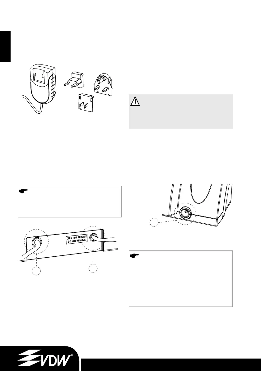
1. Select the plug adapter that matches your
electric power outlet for the power supply.
Place the required plug adapter on the two con-
tacts on the power supply and push it toward the
locking button until it snaps into place. You must
press the locking button to change the adapter
(Fig. 1).
NOTE
The connectors are coded. Therefore, make
sure that the connectors are correctly
oriented when plugging them together.
The VDW.SILVER
®
is provided with an USB
socket for exclusive use by an authorized service
center for maintenance purposes or software
updates. This USB socket is covered by an “ONLY
FOR SERVICE DO NOT REMOVE” label upon de-
livery.
Fig. 1 Plug adapters for power supply
2. Charge the battery before the first use (see
chapter 7.3.3.):
a. Connect the battery charger to the mains.
b. Insert the connector of the battery charger in
jack connector (A – see Fig. 2) at the back of the
device (for details see chapter 7.3.3.).
c. Completely charge the battery prior to first use.
d. Plug the foot pedal cable into the jack, located
on the back of the device (C – see Fig. 2).
WARNING
To disconnect the cables, always hold at
the central part of the connector and pull
out. Do not pull the cable.
7.3.2. Micromotor
3. Insert the micromotor connector into the 9-pin
metal socket (B - see Fig. 3) at the front of the
device.
NOTE
The connector B is a push-pull connector.
Align the red dot on top of the male connector
to the upright position to fit the guide on
the female connector. Do not screw into the
connector. To disconnect, pull out using the
metal end of the cable. Do not twist in any
direction.
4. Attach the VDW Endo 6:1 contra-angle to the
micromotor (see separate contra-angle operation
instructions).
5. Disinfect the keypad and micromotor before
first use and before each use on a new patient
(for details see chapter 7.8.)
Fig. 3 Metal socket
A
C
B
Fig. 2 Back of central unit
9.6.11_VDW.SILVER_RECIPROC Upgrade Stick_inhalt.indd 289.6.11_VDW.SILVER_RECIPROC Upgrade Stick_inhalt.indd 28 09.06.2011 17:18:0109.06.2011 17:18:01
 Loading...