EasyManua.ls Logo

Vector 4 - Page 100

Vector 4
227 pages
Print Icon
To Next Page IconTo Next Page
To Previous Page IconTo Previous Page
Loading...
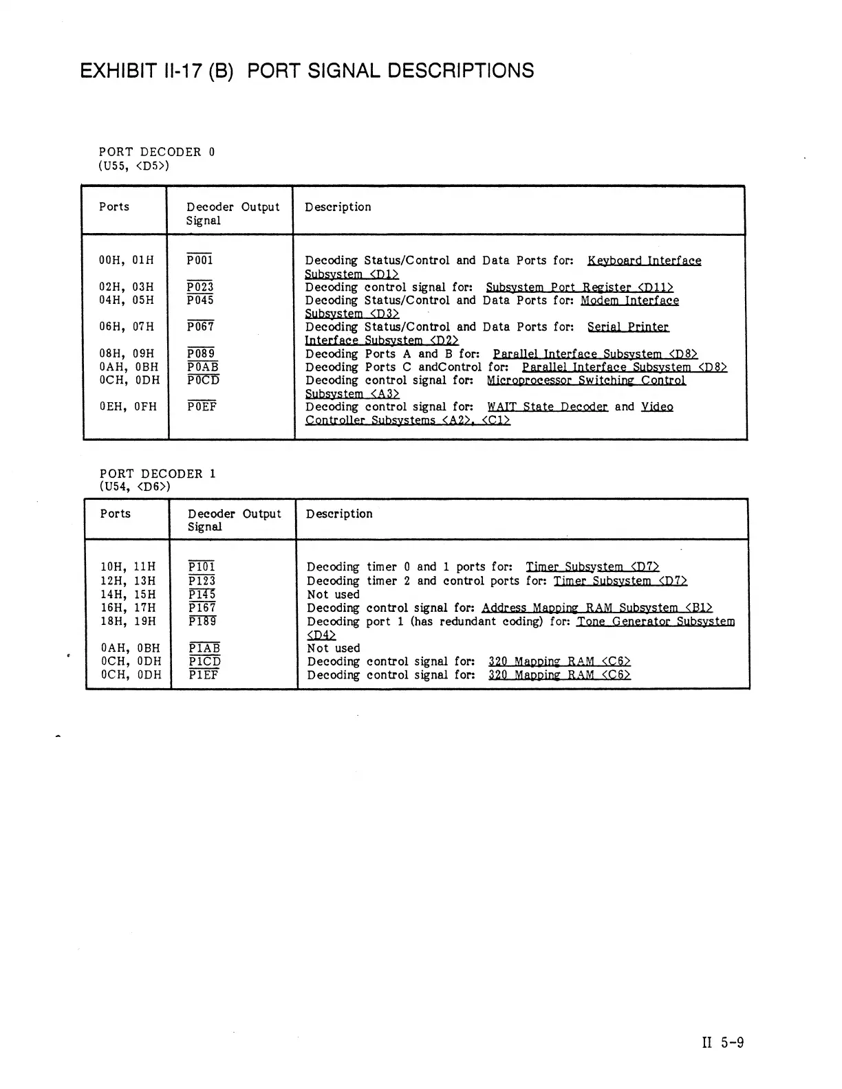
EXHIBIT
1I-17
(B)
PORT
SIGNAL
DESCRIPTIONS
PORT
DECODER
0
(US55,
<D5>)
Ports
Decoder
Output
Description
Signal
00H,
01H
001
Decoding
Status/Control
and
Data
Ports
for:
Keyboard
Interface
_
Subsystem
<D1>
02H,
03H
P023
Decoding
control
signal
for:
Subsystem
Port
Register
<D11>
04H,
05H
P045
Decoding
Status/Control
and
Data
Ports
for:
Modem
Interface
R
Subsystem
<D3>
06H,
07TH
P067
Decoding
Status/Control
and
Data
Ports
for:
Serial
Printer
Interface
Subsystem
<D2>
08H,
09H
P089
Decoding
Ports
A
and
B
for:
Parallel
Interface
Subsystem
<D8>
0AH,
0BH
POAB
Decoding
Ports
C
andControl
for:
Parallel
Interface
Subsystem
<D8>
0CH,
0DH
POCD
Decoding
control
signal
for:
Microprocessor
Switehing
Control
.
Subsystem
<A3>
0EH,
OFH
POEF
Decoding
control
signal
for:
WAIT
State
Decoder
and
Yideo
Controller
Subsystems
<A22,
<Cl1>
PORT
DECODER
1
(US54,
<D6>)
Ports
Decoder
Output
Description
Signal
10H,
11H
PI01
Decoding
timer
0
and
1
ports
for:
Timer
Subsystem
<D7>
12H,
13H
P123
Decoding
timer
2
and
control
ports
for:
Timer
Subsystem
<D7>
14H,
15H
P145%
Not
used
16H,
17H
P167
Decoding
control
signal
for:
Address
Mapping
RAM
Subsystem
<Bl>
18H,
19H
P189
Decoding
port
1
(has
redundant
coding)
for:
Tone
Generator
Subsystem
.
<D4>
0AH,
0BH
P1AB
Not
used
0CH,
0DH
P1CD
Decoding
control
signal
for:
320
Mapping
RAM
<C6>
0CH,
0DH
P1EF
Decoding
control
signal
for:
320
Mapping
RAM
<C6>
I
5-9