EasyManua.ls Logo

Vector 4 - Page 99

Vector 4
227 pages
Print Icon
To Next Page IconTo Next Page
To Previous Page IconTo Previous Page
Loading...
EXHIBIT
I-17
(A)
PORT
SIGNAL
DESCRIPTIONS
PORT
DECODER
OPERATION
Port
Decoder
0
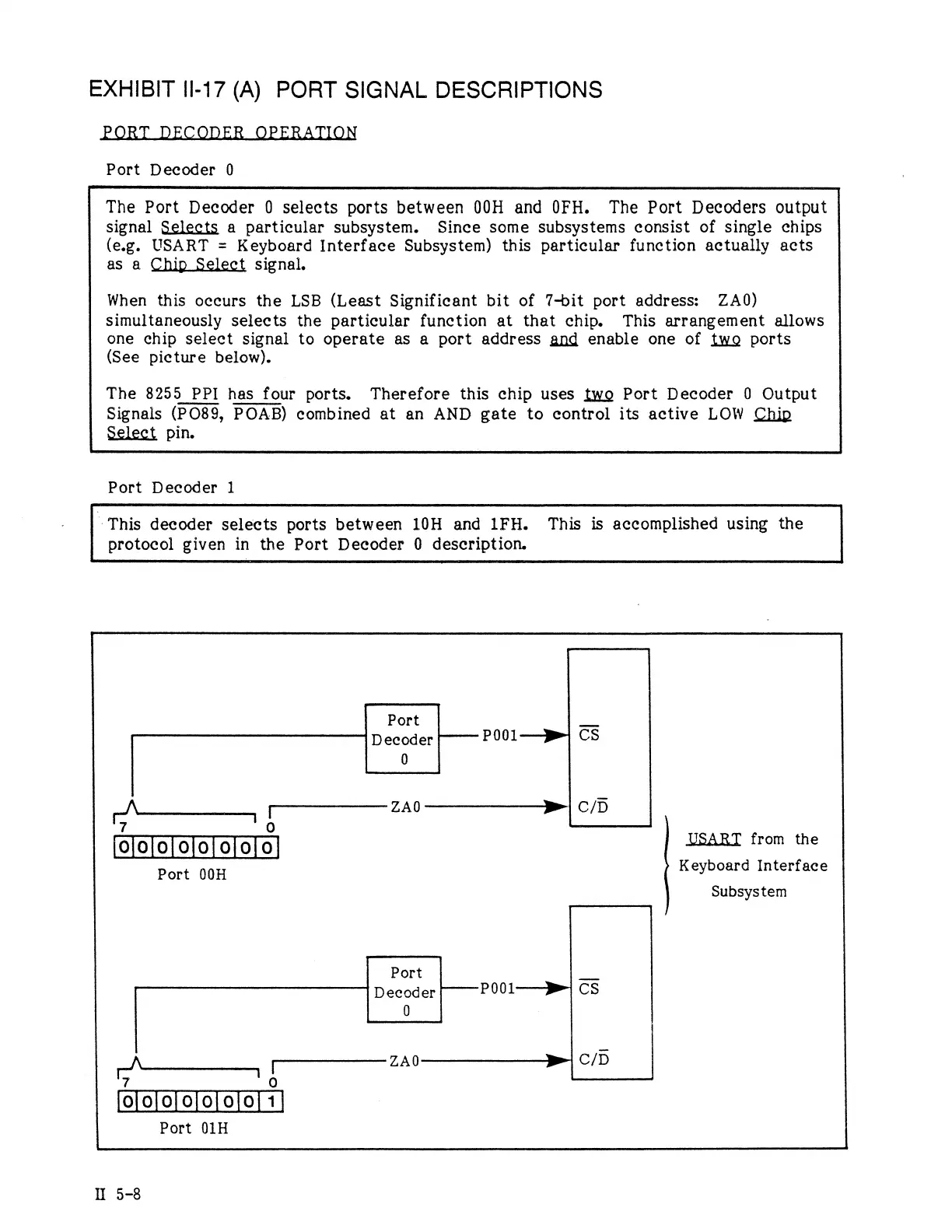
The
Port
Decoder
0
selects
ports
between
00H
and
0FH.
The
Port
Decoders
output
signal
Selects
a
particular
subsystem.
Since
some
subsystems
consist
of
single
chips
(e.g.
USART
=
Keyboard
Interface
Subsystem)
this
particular
function
actually
acts
as
a
Chip
Select
signal.
When
this
occurs
the
LSB
(Least
Significant
bit
of
7-bit
port
address:
ZAO0)
simultaneously
selects
the
particular
function
at
that
chip.
This
arrangement
allows
one
chip
select
signal
to
operate
as
a
port
address
gnd
enable
one
of
fwo
ports
(See
picture
below).
The
8255
PPI
has
four
ports.
Therefore
this
chip uses
fwo
Port
Decoder
0
Output
Signals
(PO89,
POAB)
combined
at
an
AND
gate
to
control
its
active
LOW
Chip
Select
pin.
Port
Decoder
1
"
This
decoder
selects
ports
between
10H
and
1FH.
This
is
accomplished
using
the
protocol
given
in
the
Port
Decoder
0
description.
Port
.
Decoder
——
P001—p»1
CS
0
r‘A
[
ZA0
|
C/D
7
!
0
|ojojo]ololo]o]0]
USART
from
the
Port
00H
Keyboard
Interface
Subsystem
Port
L
|
Decoder
——P001—»
CS
)\
[
ZAOQ
P
C/D
7
"o
l0jlojojojolo]o]f
1]
Port
01H
I
5-8