EasyManua.ls Logo

Vector 4 - Page 202

Vector 4
227 pages
Print Icon
To Next Page IconTo Next Page
To Previous Page IconTo Previous Page
Loading...
UPDATES
1.
The
FD
and
FD/HD
Controller
Board
Schematies
(Exhibit
VI-12
'and
Exhibit
VI-13)
were
not
completed
at
press
time.
They
will'be
mailed
to
all
VECTOR
Dealers
when
they
become
available.
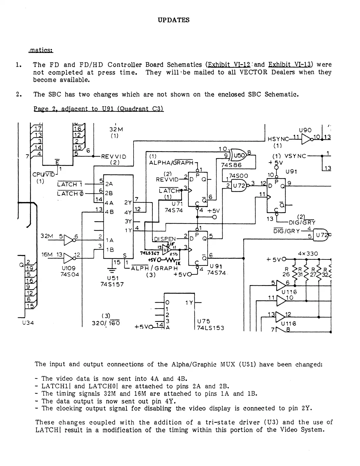
2.
The
SBC
has
two
changes
which
are
not
shown
on
the
enclosed
SBC
Schematic.
Page
2,
adjacent
to
U91
(Quadrant
C3)
/
1
.
/].Z.
32M
uso
‘
/l%
:
(1)
HSYNGC
‘
14
15
10,
(1)
7K'£L
_
REVVID
(1)
__9_)
(1)
VSYNC
1
j:
(2)
ALPHA/GRAPH
24SB6
+
5V
113
1
o=
.
91
CPUVTD
(2)
105
Y
1)
———
|
s
REVVID—&{D
17330
=g
CATCH
1
2A
2|u72
D'
qf2
CATCH
®
—H2{28
AN
11
13148
4yH2
74574
4
+5v
C
|
+—0
(2)
__
—
3Y
—
13LDIG/GRY
/
4
|
1
——
4
32M
5\_6
2
v
2
’
2
D‘G/GRY-—?@D
___{>c
2
D
Q
1A
3
—_—
16M
13D
12
r—
e
S
LS
36T
>
ale
4x330
alke
_Ds
L1________“5V
T
+
5V
19,
U109
L
ALPH
/GRAPH
a2
Yol
R
DR
ROR<
(5
A
74504
=
(3)
+5Yv
74574,
26
D3N
22732
US1
|
Lo
745157
SIN\6
|
=
L2
|12
1
U116
6
11
N\10
=y
—0
1Y}~
17
h-ly
—--11
—
(3)
—2
le
U34
320/
160
7713
u75s
U118
/-
+5Vvo-13{a
74L5153
NG
The
input
and
output
connections
of
the
Alpha/Graphic
MUX
(U51)
have been
changed:
The
video
data
is
now
sent
into
4A
and
4B.
LATCHI1|
and
LATCHO|
are
attached
to
pins
2A
and
2B.
The
timing
signals
32M
and
16M
are
attached
to
pins
1A
and
1B.
The
data
output
is
now
sent
out
pin
4Y.
The
clocking
output
signal
for
disabling
the
video
display
is
connected
to
pin
2Y.
These
changes
coupled
with
the
addition
of
a
tri-state
driver
(U3)
and
the
use
of
LATCH]|
result
in
a
modification
of
the
timing
within
this
portion
of
the
Video
System.